Refer to the illustration alongside of a proposed refrigeration system operating with R-134a
Refrigeration cycle
Refer to the illustration alongside of a proposed refrigeration system operating with R-134a, the most widely used commercial and domestic refrigerant. R-134a enters the compressor at T1 = -16°C and x1 = 1.0. The volume flow rate is 1 m3/minute. The refrigerant leaves the condenser at T3 = 40°C and p3 = 1 MPa.
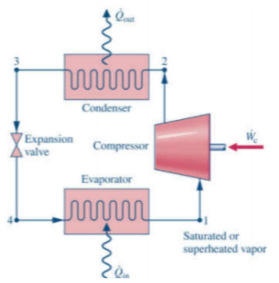
2.4. Calculate the “refrigeration capacity” (also called the “cooling load”).
2.5. Calculate the system's coefficient of performance (COP) and compare that to the COP of a Carnot-refrigerator. What conclusion can you draw? (i.e., is the proposed refrigeration cycle viable or not?)
Homework Answers


Add Answer to:
Refer to the illustration alongside of a proposed refrigeration system operating with R-134a
A freezer is designed, based on vapor-compression refrigeration cycle. The designed conditions are: R-134a as refrigerant,...
A freezer is designed, based on vapor-compression refrigeration cycle. The designed conditions are: R-134a as refrigerant, with a cooling capacity of 500 kW; compressor of 70% efficiency, with a superheat of 10°C before compressor inlet; operation temperature of -10°C inside the refrigerator, with the environment temperature of 25°C outside the refrigerator; Determine the pressure range of refrigeration cycle if a 10°C difference is required to ensure effective heat transfer of evaporator and condenser; Plot the refrigeration cycle on P-h diagram;...
A commercial refrigerator with refrigerant-134a as the working fluid is used to keep the refrigerated space at by The refrigerant enters the condenser at compressor consumes 3.3 kW of power, dete...
 A commercial refrigerator with refrigerant-134a as the working fluid is used to keep the refrigerated space at by The refrigerant enters the condenser at compressor consumes 3.3 kW of power, determine (a) the mass flow rate of the refrigerant, (b) the refrigeration load, (e) the COP, and (d) the g waste heat to cooling water that enters the condenser at 18°C at a rate of 0.25 kg/s and leaves at 26°C. 1.2 MPa and 50°C and leaves at the same...
A Refrigeration System Using R-134A In a refrigeration system, the refrigerant R-134A begins as s...
 A Refrigeration System Using R-134A In a refrigeration system, the refrigerant R-134A begins as saturated vapor at -15°(State 1). It then goes through a reversible adiabatic compressor to reach State 2. After flowing through the condenser (a heat exchanger), the refrigerant exits as saturated liquid at 70°C (State 3). It is then throttled by going through an expansion valve, to reach State 4. It finishes the cycle by going through another heat exchanger (the evaporator), to return to State 1....
Problem #4 (20 points) A commercial refrigerator with refrigerant-134a as the working fluid is used to...
 Problem #4 (20 points) A commercial refrigerator with refrigerant-134a as the working fluid is used to keep the refrigerated space at -30°C by rejecting its waste heat to cooling water that enters the condenser at 18°C at a rate of 0.25 kg/s and leaves at 26°C. The refrigerant enters the condenser at 1.2 MPa and 65°C and leaves at 42°C. The inlet state of the compressor is 60 kPa and-34°Cand the compressor is estimated to gain a net heat of...
A commercial refrigerator with refrigerant-134a as the working fluid is used to keep the refrigerated space...
A commercial refrigerator with refrigerant-134a as the working fluid is used to keep the refrigerated space at −25°C by rejecting waste heat to cooling water that enters the condenser at 20°C at a rate of 0.25 kg/s and leaves at 26°C. The refrigerant enters the condenser at 1.2 MPa and 50°C and leaves at the same pressure subcooled by 5°C. If the compressor consumes 3.3 kW of power, determine (a) the mass flow rate of the refrigerant, (b) the refrigeration...
Consider a two-stage cascade refrigeration system operating between the pressure limits of 1 MPa and 180...
Consider a two-stage cascade refrigeration system operating between the pressure limits of 1 MPa and 180 kPa with refrigerant-134a as the working fluid. The refrigerant leaves the condenser as a saturated liquid and is throttled to a flash chamber operating at 0.4 MPa. Part of the refrigerant evaporates during this flashing process, and this vapor is mixed with the refrigerant leaving the low-pressure compressor. The mixture is then compressed to the condenser pressure by the high-pressure compressor. The liquid in...
The mass flow rate of R-134a in a vapor-compression refrigeration cycle is 6 kg/min
The mass flow rate of R-134a in a vapor-compression refrigeration cycle is 6 kg/min. At the inlet of the compressor, R-134a is at -10°C, 150 kPa. The pressure at the compressor exit is 600 kPa. The compressor has an isentropic efficiency of 67%. The refrigerant leaves the condenser at 20°C. Neglect any pressure drops in the condenser, the evaporator, and pipes. Assume an adiabatic compressor. (a)draw the cycle and the T-s diagram of the cycle. Also find: (b)the coefficient of the performance...
A two-stage compression refrigeration system with an adiabatic liquid-vapor separation unit uses refrigerant-134a as working fluid....
 A two-stage compression refrigeration system with an adiabatic liquid-vapor separation unit uses refrigerant-134a as working fluid. The system operates the evaporator at 0.4 MPa, the condenser at 1.6 MPa, and the separator at 0.8 MPa. The compressors use 25 kW of power. Given that the refrigerant is saturated liquid at the inlet of each expansion valve and saturated vapor at the inlet of each compressor, and the compressors are isentropic: (0) show the process on a T-s diagram; ) calculate...
An ideal vapor-compression refrigeration cycle that uses refrigerant R-134a as its working fluid maintains a condenser...
 An ideal vapor-compression refrigeration cycle that uses refrigerant R-134a as its working fluid maintains a condenser at 800 kPa and the evaporator at -12C. (a) Determine this system's COP and the amount of power required to service a 150kW cooling load. (b) Determine the P,T, h, S and exergy of R-134a at all four states of the entire cycle. Assume the ambient temperature to be 25C.
A vapor compression refrigeration cycle utilizes R-134a as the working fluid. The refrigerant flow rate is 50 g/s. Vapor at 150 kPa and -10 0C enters the compressor and leaves at 1.2 MPa and 75 0C. Th...
A vapor compression refrigeration cycle utilizes R-134a as the working fluid. The refrigerant flow rate is 50 g/s. Vapor at 150 kPa and -10 0C enters the compressor and leaves at 1.2 MPa and 75 0C. The power input to the non-adiabatic compressor is measured and found to be 2.4 kW. The refrigerant enters the expansion valve at 1.15 MPa and 40 0C and leaves the evaporator at 160 kPa and -15 0C. Determine the entropy generation in the compression...
 A commercial refrigerator with refrigerant-134a as the working fluid is used to keep the refrigerated space at by The refrigerant enters the condenser at compressor consumes 3.3 kW of power, determine (a) the mass flow rate of the refrigerant, (b) the refrigeration load, (e) the COP, and (d) the g waste heat to cooling water that enters the condenser at 18°C at a rate of 0.25 kg/s and leaves at 26°C. 1.2 MPa and 50°C and leaves at the same...
 A Refrigeration System Using R-134A In a refrigeration system, the refrigerant R-134A begins as saturated vapor at -15°(State 1). It then goes through a reversible adiabatic compressor to reach State 2. After flowing through the condenser (a heat exchanger), the refrigerant exits as saturated liquid at 70°C (State 3). It is then throttled by going through an expansion valve, to reach State 4. It finishes the cycle by going through another heat exchanger (the evaporator), to return to State 1....
 Problem #4 (20 points) A commercial refrigerator with refrigerant-134a as the working fluid is used to keep the refrigerated space at -30°C by rejecting its waste heat to cooling water that enters the condenser at 18°C at a rate of 0.25 kg/s and leaves at 26°C. The refrigerant enters the condenser at 1.2 MPa and 65°C and leaves at 42°C. The inlet state of the compressor is 60 kPa and-34°Cand the compressor is estimated to gain a net heat of...
 A two-stage compression refrigeration system with an adiabatic liquid-vapor separation unit uses refrigerant-134a as working fluid. The system operates the evaporator at 0.4 MPa, the condenser at 1.6 MPa, and the separator at 0.8 MPa. The compressors use 25 kW of power. Given that the refrigerant is saturated liquid at the inlet of each expansion valve and saturated vapor at the inlet of each compressor, and the compressors are isentropic: (0) show the process on a T-s diagram; ) calculate...
 An ideal vapor-compression refrigeration cycle that uses refrigerant R-134a as its working fluid maintains a condenser at 800 kPa and the evaporator at -12C. (a) Determine this system's COP and the amount of power required to service a 150kW cooling load. (b) Determine the P,T, h, S and exergy of R-134a at all four states of the entire cycle. Assume the ambient temperature to be 25C.
Most questions answered within 3 hours.
-
Where is the error in this code sequence?
String s1 = "Hello";
String s2 = "ello";...
asked 11 months ago -
Financial data for Joel de Paris, Inc., for last year
follow:
Joel de Paris, Inc.
Balance...
asked 11 months ago -
Consider this reaction:
Al2(SO4)3 (aq)+ BaCl3
(aq) Al2Cl6 (aq)- +
3BaSO4(s) . What is the...
asked 11 months ago -
Suppose that Savneet is considering increasing her
recent random sample from 20 car rentals to 40...
asked 11 months ago -
Trucks arrive at an unloading terminal at an average rate of 120
per hour.
Trucks arrive...
asked 11 months ago -
Why are methanol and ethanol completely soluble in water while
octanol is not very little soluble....
asked 11 months ago -
A facilities manager at a university reads in a research report
that the mean amount of...
asked 11 months ago -
When the CuSO4 is rehydrated by adding water to the anhydrous
compound, is this an endothermic...
asked 11 months ago -
A ray of sunlight is passing from diamond into crown glass; the
angle of incidence is...
asked 11 months ago -
A block of mass 0.249 kg is placed on top of a light, vertical
spring of...
asked 11 months ago -
how do the kidneys compensate in the presences of acidosis
a) trigger hyperventilate
b) reserve acid...
asked 11 months ago -
Question 501 pts
The rental rate of capital to the firm increases. Which of the
following...
asked 11 months ago