
Homework Answers


Add Answer to:
3. Figure Q.3 shows the undercarriage of a drone aircraft, made of a hollow circular pipe...
SX= 204MPa SY= -12MPa 2. Figure 2 shows a tubular joint subjected to moment M and...
 SX= 204MPa
SY= -12MPa
2. Figure 2 shows a tubular joint subjected to moment M and P. Due to these CLO4 loads, an element of the joint in xy plane ABCD has stress system shown in Figure 3. The values of the stresses are Oxx = SX , Oyy = SY, and Txy = 45 MPa. The values and units of measure for the stresses are as given in the data sheet. Construct Mohr's circle for the stress systems to...
SX= 204MPa
SY= -12MPa
2. Figure 2 shows a tubular joint subjected to moment M and P. Due to these CLO4 loads, an element of the joint in xy plane ABCD has stress system shown in Figure 3. The values of the stresses are Oxx = SX , Oyy = SY, and Txy = 45 MPa. The values and units of measure for the stresses are as given in the data sheet. Construct Mohr's circle for the stress systems to...
3. Figure shows a state of plane stress consists of normal stresses 60 MPa and Ly-40MPa;...
 3. Figure shows a state of plane stress consists of normal stresses 60 MPa and Ly-40MPa; and unknown shear stress, The maximum principal stress was determined to be 104.34 MPa. Using Mohr's cirdle, determine a. the magnitude of the shear stress, b. the principal plane and the minimum principal stress. Then, sketch the element showing all stresses in its proper orientation, c. the maximum shear stress, associated normal stress and the orientation of the element. Then, sketch the element showing...
- P12.44 Figure P12.44 shows Mohr's circle for a point in a phys- ical object that...
 - P12.44 Figure P12.44 shows Mohr's circle for a point in a phys- ical object that is subjected to plane stress. (a) Determine the stresses Oy Oy, and Try and show them on a stress element. (b) Determine the principal stresses and the maximum in-plane shear stress acting at the point, and show these stresses on an appropriate sketch (e.g., see Figure 12.15 or Figure 12.16). I grid square = 10 MPa FIGURE P12.44 112.44 a) From graph: Tx 80...
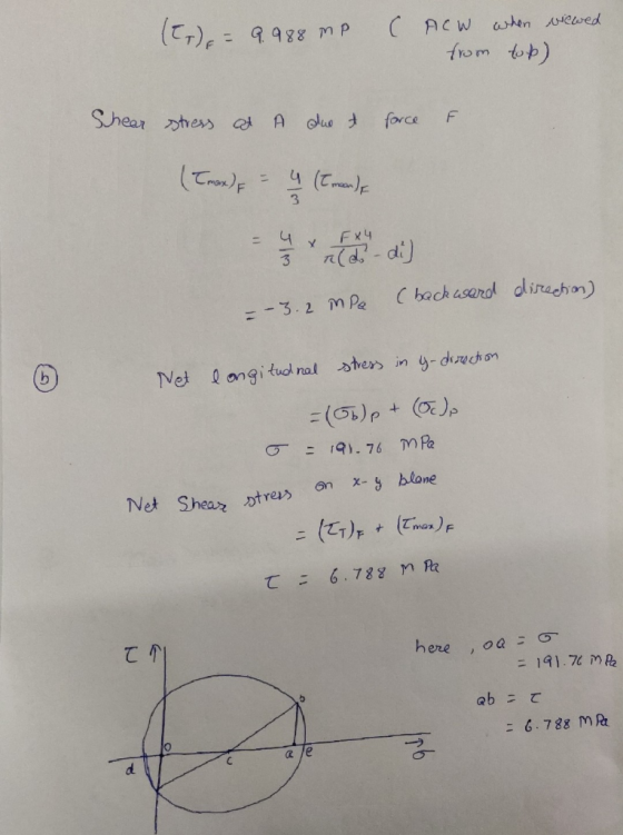
Explain brifly and calculate "part B" directly Section 2.4 2.60 Figure P2.60 shows a static force,...
 Explain brifly and calculate "part B" directly
Section 2.4 2.60 Figure P2.60 shows a static force, F applied to the tooth of a gear that is keyed to a shaft. Making appropriate simplifying assumptions, identify the stresses in the key. and write an equation for each.* State the assumptions made, and discuss briefly their effect Section on A-4 FIGURE P2.60 Part B. If in above example, the static force F = 25,000 N is acting at a distance of R...
Explain brifly and calculate "part B" directly
Section 2.4 2.60 Figure P2.60 shows a static force, F applied to the tooth of a gear that is keyed to a shaft. Making appropriate simplifying assumptions, identify the stresses in the key. and write an equation for each.* State the assumptions made, and discuss briefly their effect Section on A-4 FIGURE P2.60 Part B. If in above example, the static force F = 25,000 N is acting at a distance of R...
Question 3 (1) Figure Q3(a) shows the stresses at a point in a structure. Using the...
 Question 3 (1) Figure Q3(a) shows the stresses at a point in a structure. Using the Mohr's circle, determine the maximum in-plane shear stress of the point and shown it on a sketch of a properly oriented stress element. 12 marks) 50 MPa 30 MPa 30 MPa Figure Q3(a) (2) The 50-mm-diameter solid shaft shown in Figure Q3(b) is fixed at B and subject to the couple forces at the top through a rigid wrench. Determine the maximum shear stres...
the steel lever shown in figure is loaded by a vertical force f=2000 N. A stress...
 the steel lever shown in figure
is loaded by a vertical force f=2000 N. A stress element is located
on the upper side of the lever at A (on the smaller diameter) as
shown .Draw the stress element at A showing the magnitude and
directions of the stresses acting on it and find the principal
stresses and directions.
Problem 3 The steel lever shown in figure is loaded by a vertical force F = 2000 N A stress element is...
the steel lever shown in figure
is loaded by a vertical force f=2000 N. A stress element is located
on the upper side of the lever at A (on the smaller diameter) as
shown .Draw the stress element at A showing the magnitude and
directions of the stresses acting on it and find the principal
stresses and directions.
Problem 3 The steel lever shown in figure is loaded by a vertical force F = 2000 N A stress element is...
3 (15 points) A bent circular cantilever beam of uniform diameter of 25 mm is shown in igure below. The beam is made from a material with elastic modulus is 70 GPa, the tensile strength is 250 M...
 3 (15 points) A bent circular cantilever beam of uniform diameter of 25 mm is shown in igure below. The beam is made from a material with elastic modulus is 70 GPa, the tensile strength is 250 MPa, and the ultimate strength is 300 MPa. 250 mm A. 150 mm z Zz. 50N V (z direction) 100 N (a) (5 points) What are the stresses in the beam at point A? (b) (10 points) Based on your calculations in (a),...
3. A beam with a hollow circular cross section of outer diameter D and inner diameter...
 3. A beam with a hollow circular cross section of outer diameter D and inner diameter d. The length Lis fixed at a wall. Consider the following loading conditions, all applied to the beam at the midpoint of length L. For each loading scheme state determine the magnitude of that stress in terms of the variables given in the problem). (5 points) i. ii. iii. iv. V. Normal stress due to axial load F Shear stress due to torque T...
P = 0.44 MPa T = 108 kN•m h = 2.4mm Common Data: [Young’s modulus, E=210...
 P = 0.44 MPa
T = 108 kN•m
h = 2.4mm
Common Data: [Young’s modulus, E=210
GN/m2] [Poisson’s ratio, ν=0.33] [Yield
stress σ0 = 210 MN/m2 ]
Figure 1(A) through to (F) shows a pressure vessel. During a test program to determine its capacity, it is subjected to a combined internal pressure, P and torsion, T. The vessel has an external diameter, D = 1 m, length 3 m, and the wall thickness is h mm. Considering the wall is thin,...
P = 0.44 MPa
T = 108 kN•m
h = 2.4mm
Common Data: [Young’s modulus, E=210
GN/m2] [Poisson’s ratio, ν=0.33] [Yield
stress σ0 = 210 MN/m2 ]
Figure 1(A) through to (F) shows a pressure vessel. During a test program to determine its capacity, it is subjected to a combined internal pressure, P and torsion, T. The vessel has an external diameter, D = 1 m, length 3 m, and the wall thickness is h mm. Considering the wall is thin,...
 SX= 204MPa
SY= -12MPa
2. Figure 2 shows a tubular joint subjected to moment M and P. Due to these CLO4 loads, an element of the joint in xy plane ABCD has stress system shown in Figure 3. The values of the stresses are Oxx = SX , Oyy = SY, and Txy = 45 MPa. The values and units of measure for the stresses are as given in the data sheet. Construct Mohr's circle for the stress systems to...
SX= 204MPa
SY= -12MPa
2. Figure 2 shows a tubular joint subjected to moment M and P. Due to these CLO4 loads, an element of the joint in xy plane ABCD has stress system shown in Figure 3. The values of the stresses are Oxx = SX , Oyy = SY, and Txy = 45 MPa. The values and units of measure for the stresses are as given in the data sheet. Construct Mohr's circle for the stress systems to...
 3. Figure shows a state of plane stress consists of normal stresses 60 MPa and Ly-40MPa; and unknown shear stress, The maximum principal stress was determined to be 104.34 MPa. Using Mohr's cirdle, determine a. the magnitude of the shear stress, b. the principal plane and the minimum principal stress. Then, sketch the element showing all stresses in its proper orientation, c. the maximum shear stress, associated normal stress and the orientation of the element. Then, sketch the element showing...
 - P12.44 Figure P12.44 shows Mohr's circle for a point in a phys- ical object that is subjected to plane stress. (a) Determine the stresses Oy Oy, and Try and show them on a stress element. (b) Determine the principal stresses and the maximum in-plane shear stress acting at the point, and show these stresses on an appropriate sketch (e.g., see Figure 12.15 or Figure 12.16). I grid square = 10 MPa FIGURE P12.44 112.44 a) From graph: Tx 80...
 Explain brifly and calculate "part B" directly
Section 2.4 2.60 Figure P2.60 shows a static force, F applied to the tooth of a gear that is keyed to a shaft. Making appropriate simplifying assumptions, identify the stresses in the key. and write an equation for each.* State the assumptions made, and discuss briefly their effect Section on A-4 FIGURE P2.60 Part B. If in above example, the static force F = 25,000 N is acting at a distance of R...
Explain brifly and calculate "part B" directly
Section 2.4 2.60 Figure P2.60 shows a static force, F applied to the tooth of a gear that is keyed to a shaft. Making appropriate simplifying assumptions, identify the stresses in the key. and write an equation for each.* State the assumptions made, and discuss briefly their effect Section on A-4 FIGURE P2.60 Part B. If in above example, the static force F = 25,000 N is acting at a distance of R...
 Question 3 (1) Figure Q3(a) shows the stresses at a point in a structure. Using the Mohr's circle, determine the maximum in-plane shear stress of the point and shown it on a sketch of a properly oriented stress element. 12 marks) 50 MPa 30 MPa 30 MPa Figure Q3(a) (2) The 50-mm-diameter solid shaft shown in Figure Q3(b) is fixed at B and subject to the couple forces at the top through a rigid wrench. Determine the maximum shear stres...
 the steel lever shown in figure
is loaded by a vertical force f=2000 N. A stress element is located
on the upper side of the lever at A (on the smaller diameter) as
shown .Draw the stress element at A showing the magnitude and
directions of the stresses acting on it and find the principal
stresses and directions.
Problem 3 The steel lever shown in figure is loaded by a vertical force F = 2000 N A stress element is...
the steel lever shown in figure
is loaded by a vertical force f=2000 N. A stress element is located
on the upper side of the lever at A (on the smaller diameter) as
shown .Draw the stress element at A showing the magnitude and
directions of the stresses acting on it and find the principal
stresses and directions.
Problem 3 The steel lever shown in figure is loaded by a vertical force F = 2000 N A stress element is...
 3 (15 points) A bent circular cantilever beam of uniform diameter of 25 mm is shown in igure below. The beam is made from a material with elastic modulus is 70 GPa, the tensile strength is 250 MPa, and the ultimate strength is 300 MPa. 250 mm A. 150 mm z Zz. 50N V (z direction) 100 N (a) (5 points) What are the stresses in the beam at point A? (b) (10 points) Based on your calculations in (a),...
 3. A beam with a hollow circular cross section of outer diameter D and inner diameter d. The length Lis fixed at a wall. Consider the following loading conditions, all applied to the beam at the midpoint of length L. For each loading scheme state determine the magnitude of that stress in terms of the variables given in the problem). (5 points) i. ii. iii. iv. V. Normal stress due to axial load F Shear stress due to torque T...
 P = 0.44 MPa
T = 108 kN•m
h = 2.4mm
Common Data: [Young’s modulus, E=210
GN/m2] [Poisson’s ratio, ν=0.33] [Yield
stress σ0 = 210 MN/m2 ]
Figure 1(A) through to (F) shows a pressure vessel. During a test program to determine its capacity, it is subjected to a combined internal pressure, P and torsion, T. The vessel has an external diameter, D = 1 m, length 3 m, and the wall thickness is h mm. Considering the wall is thin,...
P = 0.44 MPa
T = 108 kN•m
h = 2.4mm
Common Data: [Young’s modulus, E=210
GN/m2] [Poisson’s ratio, ν=0.33] [Yield
stress σ0 = 210 MN/m2 ]
Figure 1(A) through to (F) shows a pressure vessel. During a test program to determine its capacity, it is subjected to a combined internal pressure, P and torsion, T. The vessel has an external diameter, D = 1 m, length 3 m, and the wall thickness is h mm. Considering the wall is thin,...
Most questions answered within 3 hours.
-
Where is the error in this code sequence?
String s1 = "Hello";
String s2 = "ello";...
asked 11 months ago -
Financial data for Joel de Paris, Inc., for last year
follow:
Joel de Paris, Inc.
Balance...
asked 11 months ago -
Consider this reaction:
Al2(SO4)3 (aq)+ BaCl3
(aq) Al2Cl6 (aq)- +
3BaSO4(s) . What is the...
asked 11 months ago -
Suppose that Savneet is considering increasing her
recent random sample from 20 car rentals to 40...
asked 11 months ago -
Trucks arrive at an unloading terminal at an average rate of 120
per hour.
Trucks arrive...
asked 11 months ago -
Why are methanol and ethanol completely soluble in water while
octanol is not very little soluble....
asked 11 months ago -
A facilities manager at a university reads in a research report
that the mean amount of...
asked 11 months ago -
When the CuSO4 is rehydrated by adding water to the anhydrous
compound, is this an endothermic...
asked 11 months ago -
A ray of sunlight is passing from diamond into crown glass; the
angle of incidence is...
asked 11 months ago -
A block of mass 0.249 kg is placed on top of a light, vertical
spring of...
asked 11 months ago -
how do the kidneys compensate in the presences of acidosis
a) trigger hyperventilate
b) reserve acid...
asked 11 months ago -
Question 501 pts
The rental rate of capital to the firm increases. Which of the
following...
asked 11 months ago