
Homework Answers
Add Answer to:
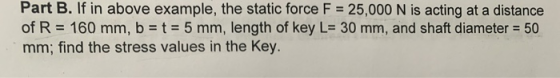
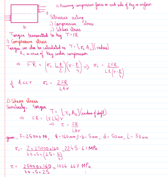
Explain brifly and calculate "part B" directly
Section 2.4 2.60 Figure P2.60 shows a static force,...
3- The shaft shown in the figure rotates with constant angular velocity and is transmitting a...
 3- The shaft shown in the figure rotates with constant angular velocity and is transmitting a torque from gear B to gear C through the forces Exo and Ez as shown. The shaft is subject to combined bending and torsion due to the forces shown. The weights of the shaft and pulleys may be neglected and the supports can exert only concentrated force reactions. The radius of the gear at B is 50 mm and that at C is 75...
Question 1 The motor shown in Fig. 1 supplies power to Gear C through solid steel...
 Question 1 The motor shown in Fig. 1 supplies power to Gear C through solid steel motor shaft GF (having a diamet of 200 mm) and Gear F. The torque delivered to Gear C is 200 kNm. Gears A, B, D and E supply powers to er three machines. The torques delivered by gear A, gear B and gear E to the machines are 60 kNm, 30 kNm and 40 kNm, respectively. Shaft ABCDE is also made of steel (G...
Please answer A and B. The rotating solid stedl shaft is simply supported by bearings at...
 Please answer A and B.
The rotating solid stedl shaft is simply supported by bearings at points B and C and is driven by a gear (not shown) which meshes with the spur gear at D, which has a 150-mm pitch diameter. The force F from the drive gear acts at a pressure angle of 20. The shaft transmits a torque to point A of TA-340 N m. The shaft is machined from steel with Sy- 420 MPa and Sut-560...
Please answer A and B.
The rotating solid stedl shaft is simply supported by bearings at points B and C and is driven by a gear (not shown) which meshes with the spur gear at D, which has a 150-mm pitch diameter. The force F from the drive gear acts at a pressure angle of 20. The shaft transmits a torque to point A of TA-340 N m. The shaft is machined from steel with Sy- 420 MPa and Sut-560...
The rotating solid steel shaft is simply supported by bearings at points B and C and is driven by gear (not shown) which meshes with the spur gear at D
 The rotating solid steel shaft is simply supported by bearings at points B and C and is driven by gear (not shown) which meshes with the spur gear at D, which has a 150-mm pitch diameter. The force F from the drive gear acts at a pressure angle of 20". The shaft transmits a torque to point A of TA = 340 N.m. The shaft is machined from steel with Sy= 420 MPa and Sut = 560 MPa. The fatigue...
The figure shows a crank loaded by a force F 300 lbr that causes twisting and...
 The figure shows a crank loaded by a force F 300 lbr that causes twisting and bending on the solid circular shaft, % in diameter, fixed to a support. For a stress element at "A" a Calculate applied bending and torsional stresses and their angles of orientation. b Draw the initial stress element. c- Draw a complete principle stress element d Draw a complete shear stress element. 1.5 in in dia. in dia in It in 4 in 5 in
1. The part shown consists of a bent rod with a solid circular cross section of...
 1. The part shown consists of a bent rod with a solid circular cross section of diameter 20 mm. Consider the cross- section on a cut at both a-a, and b-b. 400 mm A] For each cut, label the shear force, bending moments, and torsion moments. Then determine the critical point with the highest normal stress at each cross- section. No stress calculations are required. /100 mm 1 BJ Determine the point of highest normal stress for the bent rod...
The part shown in the figure has a circular cross-section of 0.04 m diameter. It is made of a steel with a yield strength of 343 MPa and an ultimate strength of 410 MPa, and is subjected to a force, F...
 The part shown in the figure has a circular cross-section of
0.04 m diameter. It is made of a steel with a yield strength of 343
MPa and an ultimate strength of 410 MPa, and is subjected to a
force, F, of 2500 N.
1. Locate the most critical point. (2 points)
2. Plot the three-dimensional stress element for that point. (2
points)
3. Calculate the values of stresses. (6 points)
Fぐ
Fぐ
The part shown in the figure has a circular cross-section of
0.04 m diameter. It is made of a steel with a yield strength of 343
MPa and an ultimate strength of 410 MPa, and is subjected to a
force, F, of 2500 N.
1. Locate the most critical point. (2 points)
2. Plot the three-dimensional stress element for that point. (2
points)
3. Calculate the values of stresses. (6 points)
Fぐ
Fぐ
Figure 1 shows the layout of countershaft used to transmit power to a blower through a...
 Figure 1 shows the layout of countershaft used to transmit power to a blower through a pulley drive (4-5). Pulley (driving sheave) 4 has a diameter of 125-mm and pulley (driven sheave) 5 has a diameter of 75 mm. Pulley 5 is mounted vertically below pulley 4 (as shown in the figure). Belt tension on the loose side is 20% of the tension on the tight side. A power of 7.5 kW is transmitted via the gear set (2-3) from...
Figure Q3 (a) shows a solid 40 mm diameter steel shaft which is supported by smooth bearings at B and D
 Figure Q3 (a) shows a solid 40 mm diameter steel shaft which is supported by smooth bearings at B and D. It is coupled to a motor at C, which delivers 6 kW of power to the shaft while it is turning at 50 Hz. The modulus of rigidity of steel is 80 GPa. The shaft is free to turn in its support bearings at B and D. If gears A and E consume powers of 2 kW and 4...
A gear reduction unit uses the countershaft shown in the figure. The solid steel shaft is...
 A gear reduction unit uses the countershaft shown in the figure. The solid steel shaft is simply supported by bearings at points O and C. Gear A receives power from another gear with the transmitted force FA applied at the 200 pressure angle as shown. The power is transmitted through the shaft and delivered through gear B through a transmitted force Fa at the pressure angle shown. 0 350 mm 225 ma Gear A 500-mm dia Gear B 200 mm...
 3- The shaft shown in the figure rotates with constant angular velocity and is transmitting a torque from gear B to gear C through the forces Exo and Ez as shown. The shaft is subject to combined bending and torsion due to the forces shown. The weights of the shaft and pulleys may be neglected and the supports can exert only concentrated force reactions. The radius of the gear at B is 50 mm and that at C is 75...
 Question 1 The motor shown in Fig. 1 supplies power to Gear C through solid steel motor shaft GF (having a diamet of 200 mm) and Gear F. The torque delivered to Gear C is 200 kNm. Gears A, B, D and E supply powers to er three machines. The torques delivered by gear A, gear B and gear E to the machines are 60 kNm, 30 kNm and 40 kNm, respectively. Shaft ABCDE is also made of steel (G...
 Please answer A and B.
The rotating solid stedl shaft is simply supported by bearings at points B and C and is driven by a gear (not shown) which meshes with the spur gear at D, which has a 150-mm pitch diameter. The force F from the drive gear acts at a pressure angle of 20. The shaft transmits a torque to point A of TA-340 N m. The shaft is machined from steel with Sy- 420 MPa and Sut-560...
Please answer A and B.
The rotating solid stedl shaft is simply supported by bearings at points B and C and is driven by a gear (not shown) which meshes with the spur gear at D, which has a 150-mm pitch diameter. The force F from the drive gear acts at a pressure angle of 20. The shaft transmits a torque to point A of TA-340 N m. The shaft is machined from steel with Sy- 420 MPa and Sut-560...
 The figure shows a crank loaded by a force F 300 lbr that causes twisting and bending on the solid circular shaft, % in diameter, fixed to a support. For a stress element at "A" a Calculate applied bending and torsional stresses and their angles of orientation. b Draw the initial stress element. c- Draw a complete principle stress element d Draw a complete shear stress element. 1.5 in in dia. in dia in It in 4 in 5 in
 1. The part shown consists of a bent rod with a solid circular cross section of diameter 20 mm. Consider the cross- section on a cut at both a-a, and b-b. 400 mm A] For each cut, label the shear force, bending moments, and torsion moments. Then determine the critical point with the highest normal stress at each cross- section. No stress calculations are required. /100 mm 1 BJ Determine the point of highest normal stress for the bent rod...
 The part shown in the figure has a circular cross-section of
0.04 m diameter. It is made of a steel with a yield strength of 343
MPa and an ultimate strength of 410 MPa, and is subjected to a
force, F, of 2500 N.
1. Locate the most critical point. (2 points)
2. Plot the three-dimensional stress element for that point. (2
points)
3. Calculate the values of stresses. (6 points)
Fぐ
Fぐ
The part shown in the figure has a circular cross-section of
0.04 m diameter. It is made of a steel with a yield strength of 343
MPa and an ultimate strength of 410 MPa, and is subjected to a
force, F, of 2500 N.
1. Locate the most critical point. (2 points)
2. Plot the three-dimensional stress element for that point. (2
points)
3. Calculate the values of stresses. (6 points)
Fぐ
Fぐ
 Figure 1 shows the layout of countershaft used to transmit power to a blower through a pulley drive (4-5). Pulley (driving sheave) 4 has a diameter of 125-mm and pulley (driven sheave) 5 has a diameter of 75 mm. Pulley 5 is mounted vertically below pulley 4 (as shown in the figure). Belt tension on the loose side is 20% of the tension on the tight side. A power of 7.5 kW is transmitted via the gear set (2-3) from...
 A gear reduction unit uses the countershaft shown in the figure. The solid steel shaft is simply supported by bearings at points O and C. Gear A receives power from another gear with the transmitted force FA applied at the 200 pressure angle as shown. The power is transmitted through the shaft and delivered through gear B through a transmitted force Fa at the pressure angle shown. 0 350 mm 225 ma Gear A 500-mm dia Gear B 200 mm...
Most questions answered within 3 hours.
-
Where is the error in this code sequence?
String s1 = "Hello";
String s2 = "ello";...
asked 10 months ago -
Financial data for Joel de Paris, Inc., for last year
follow:
Joel de Paris, Inc.
Balance...
asked 10 months ago -
Consider this reaction:
Al2(SO4)3 (aq)+ BaCl3
(aq) Al2Cl6 (aq)- +
3BaSO4(s) . What is the...
asked 10 months ago -
Suppose that Savneet is considering increasing her
recent random sample from 20 car rentals to 40...
asked 10 months ago -
Trucks arrive at an unloading terminal at an average rate of 120
per hour.
Trucks arrive...
asked 10 months ago -
Why are methanol and ethanol completely soluble in water while
octanol is not very little soluble....
asked 10 months ago -
A facilities manager at a university reads in a research report
that the mean amount of...
asked 10 months ago -
When the CuSO4 is rehydrated by adding water to the anhydrous
compound, is this an endothermic...
asked 10 months ago -
A ray of sunlight is passing from diamond into crown glass; the
angle of incidence is...
asked 10 months ago -
A block of mass 0.249 kg is placed on top of a light, vertical
spring of...
asked 10 months ago -
how do the kidneys compensate in the presences of acidosis
a) trigger hyperventilate
b) reserve acid...
asked 10 months ago -
Question 501 pts
The rental rate of capital to the firm increases. Which of the
following...
asked 10 months ago