
Homework Answers
Add Answer to:
s. ( a points) Deter ermine the points) Determine the state of stress for the following,...
For the beam shown below, find the maximum bending stress and maximum transverse shear stress. That...
 For the beam shown below, find the maximum bending stress and maximum transverse shear stress. That is, carry out load and stress analyses in the following order. Load Analysis Draw the load diagram or free body diagram (FBD) and determine the support reactions. Show your calculations. • Draw the shear force diagram (SFD). Show your calculations. Draw the bending moment diagram (BMD). Show your calculations. Stress Analysis Identify the critical section(s) and determine the maximum normal (bending) stress at the...
23 Mohrs circle The state of plane stress at a point is represented by the element...
 23 Mohrs circle The state of plane stress at a point is represented by the element shown in Fig. 2.2. Determine maximum shear stresses and the orientation, draw the stress element with the proper orientation. Determine principal stresses and the orientation, draw the stress element with the proper orientation (Note: this question is required to be solved using Mohrs circle.) Mohrs circle The state of plane stress at a point is represented by the element shown in Fig. 2.2. Determine...
The state of stress at a point is shown on the element. (a) Determine the principal...
 The state of stress at a point is shown on the element. (a) Determine the principal stress at the point. Specify the associated orientation and indicate the results on an element at the point. (b) Determine the maximum in-plane shear stress at the point. Specify the associated orientation and indicate the results on an element at the point. (c) Determine the state of stress on an element at the same point oriented 40° clockwise with respect to the element shown....
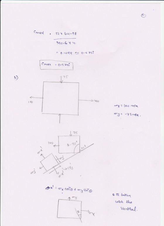
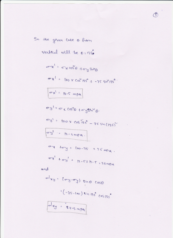
For the state of stress shown in figure (a=55 degrees), determine (a) The normal and shear...
 For the state of stress shown in figure (a=55 degrees), determine (a) The normal and shear stress acting along the oblique face of the shaded triangle (b) The state of stress, if the element were rotated by an angle 55 degrees clockwise (c) The state of stress acting on the principal normal planes (d) The state of stress acting on the principle shear planes 60 MPa - 80 MPa — x 90 MPa State of stress The state of stress...
Determine the shear stress at points A and B on the beam if it is subjected...
 Determine the shear stress at points A and B on the beam if it is subjected to a shear force of V cann 600 kN. 100 mim 00 m 100 mm 100 mm 5) 100 mm 100 mm
In the stress state shown in the element in the following figure, determine the maximum principal...
 In the stress state shown in the element in the following figure, determine the maximum principal stress (a), the angle prin in which the element must be oriented so that the maximum principal stress, the maximum shear stress (max,z) and angle max
in which the element must be oriented so that the maximum shear stress is present.
In the stress state shown in the element in the following figure, determine the maximum principal stress (a), the angle prin in which the element must be oriented so that the maximum principal stress, the maximum shear stress (max,z) and angle max
in which the element must be oriented so that the maximum shear stress is present.
S=0.5845 Please include all steps. Q2. A solid wooden beam (pine, with a maximum longitudinal stress...
 S=0.5845
Please include all steps.
Q2. A solid wooden beam (pine, with a maximum longitudinal stress 30 MPa, maximum shear stress 3 MPa and E = 9 GPa) spans a length 3L = 4.5 m (L = 1.5 m), and is supported as shown in Figure Q2. The beam is b = 10 cm wide and h = 50(1+S) cm high. The distributed force load q = 200 kN/m is applied on either side, as shown below. 21 Figure Q2...
S=0.5845
Please include all steps.
Q2. A solid wooden beam (pine, with a maximum longitudinal stress 30 MPa, maximum shear stress 3 MPa and E = 9 GPa) spans a length 3L = 4.5 m (L = 1.5 m), and is supported as shown in Figure Q2. The beam is b = 10 cm wide and h = 50(1+S) cm high. The distributed force load q = 200 kN/m is applied on either side, as shown below. 21 Figure Q2...
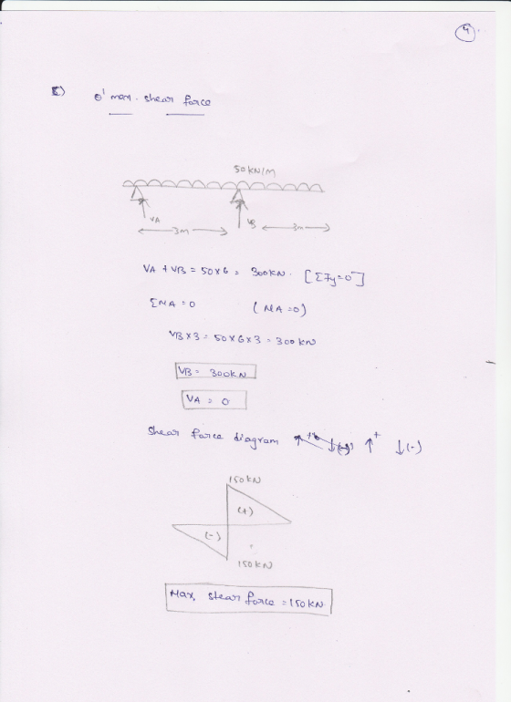
2. A cantilever beam is loaded as shown in the following figure. 1) Draw the shear...
 2. A cantilever beam is loaded as shown in the following figure. 1) Draw the shear force and bending moment diagrams 2) Calculate the maximum bending stress in the beam. S 3) Calculate themaximum transverse shear stress in the beam. 19 kN 3 kN/m NA 01 m 2 m 2 m 2 m
For the stress state shown, use Mohr's Circle to determine the following:
 For the stress state shown, use Mohr's Circle to determine the following: (a) Principal stresses σ1 and σ2, the associated shear stress τx'y', and the element orientation θp. Clearly indicate magnitude and direction. (b) Maximum in-plane shear stress τmax,in plane , the associated normal stresses σx' and σy', and the element orientation θs. Clearly indicate magnitude and direction. (c) Absolute maximum shear stress τmax,absolute · Show all work using Mohr's Circle. If your drawings do not indicate that you used Mohr's Circle appropriately, you...
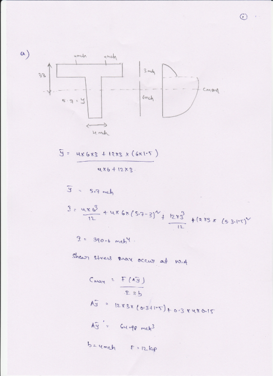
For the beam shown, determine the maximum shear stress Clearly state where this occurs. 6.5 kN/m...
 For the beam shown, determine the maximum shear stress Clearly state where this occurs. 6.5 kN/m 4 m4 m ??119.5 '5 , 150mm min 30 mm 150 mm 30 mm
 For the beam shown below, find the maximum bending stress and maximum transverse shear stress. That is, carry out load and stress analyses in the following order. Load Analysis Draw the load diagram or free body diagram (FBD) and determine the support reactions. Show your calculations. • Draw the shear force diagram (SFD). Show your calculations. Draw the bending moment diagram (BMD). Show your calculations. Stress Analysis Identify the critical section(s) and determine the maximum normal (bending) stress at the...
 23 Mohrs circle The state of plane stress at a point is represented by the element shown in Fig. 2.2. Determine maximum shear stresses and the orientation, draw the stress element with the proper orientation. Determine principal stresses and the orientation, draw the stress element with the proper orientation (Note: this question is required to be solved using Mohrs circle.) Mohrs circle The state of plane stress at a point is represented by the element shown in Fig. 2.2. Determine...
 The state of stress at a point is shown on the element. (a) Determine the principal stress at the point. Specify the associated orientation and indicate the results on an element at the point. (b) Determine the maximum in-plane shear stress at the point. Specify the associated orientation and indicate the results on an element at the point. (c) Determine the state of stress on an element at the same point oriented 40° clockwise with respect to the element shown....
 For the state of stress shown in figure (a=55 degrees), determine (a) The normal and shear stress acting along the oblique face of the shaded triangle (b) The state of stress, if the element were rotated by an angle 55 degrees clockwise (c) The state of stress acting on the principal normal planes (d) The state of stress acting on the principle shear planes 60 MPa - 80 MPa — x 90 MPa State of stress The state of stress...
 Determine the shear stress at points A and B on the beam if it is subjected to a shear force of V cann 600 kN. 100 mim 00 m 100 mm 100 mm 5) 100 mm 100 mm
 In the stress state shown in the element in the following figure, determine the maximum principal stress (a), the angle prin in which the element must be oriented so that the maximum principal stress, the maximum shear stress (max,z) and angle max
in which the element must be oriented so that the maximum shear stress is present.
In the stress state shown in the element in the following figure, determine the maximum principal stress (a), the angle prin in which the element must be oriented so that the maximum principal stress, the maximum shear stress (max,z) and angle max
in which the element must be oriented so that the maximum shear stress is present.
 S=0.5845
Please include all steps.
Q2. A solid wooden beam (pine, with a maximum longitudinal stress 30 MPa, maximum shear stress 3 MPa and E = 9 GPa) spans a length 3L = 4.5 m (L = 1.5 m), and is supported as shown in Figure Q2. The beam is b = 10 cm wide and h = 50(1+S) cm high. The distributed force load q = 200 kN/m is applied on either side, as shown below. 21 Figure Q2...
S=0.5845
Please include all steps.
Q2. A solid wooden beam (pine, with a maximum longitudinal stress 30 MPa, maximum shear stress 3 MPa and E = 9 GPa) spans a length 3L = 4.5 m (L = 1.5 m), and is supported as shown in Figure Q2. The beam is b = 10 cm wide and h = 50(1+S) cm high. The distributed force load q = 200 kN/m is applied on either side, as shown below. 21 Figure Q2...
 2. A cantilever beam is loaded as shown in the following figure. 1) Draw the shear force and bending moment diagrams 2) Calculate the maximum bending stress in the beam. S 3) Calculate themaximum transverse shear stress in the beam. 19 kN 3 kN/m NA 01 m 2 m 2 m 2 m
 For the stress state shown, use Mohr's Circle to determine the following: (a) Principal stresses σ1 and σ2, the associated shear stress τx'y', and the element orientation θp. Clearly indicate magnitude and direction. (b) Maximum in-plane shear stress τmax,in plane , the associated normal stresses σx' and σy', and the element orientation θs. Clearly indicate magnitude and direction. (c) Absolute maximum shear stress τmax,absolute · Show all work using Mohr's Circle. If your drawings do not indicate that you used Mohr's Circle appropriately, you...
 For the beam shown, determine the maximum shear stress Clearly state where this occurs. 6.5 kN/m 4 m4 m ??119.5 '5 , 150mm min 30 mm 150 mm 30 mm
Most questions answered within 3 hours.
-
Where is the error in this code sequence?
String s1 = "Hello";
String s2 = "ello";...
asked 11 months ago -
Financial data for Joel de Paris, Inc., for last year
follow:
Joel de Paris, Inc.
Balance...
asked 11 months ago -
Consider this reaction:
Al2(SO4)3 (aq)+ BaCl3
(aq) Al2Cl6 (aq)- +
3BaSO4(s) . What is the...
asked 11 months ago -
Suppose that Savneet is considering increasing her
recent random sample from 20 car rentals to 40...
asked 11 months ago -
Trucks arrive at an unloading terminal at an average rate of 120
per hour.
Trucks arrive...
asked 11 months ago -
Why are methanol and ethanol completely soluble in water while
octanol is not very little soluble....
asked 11 months ago -
A facilities manager at a university reads in a research report
that the mean amount of...
asked 11 months ago -
When the CuSO4 is rehydrated by adding water to the anhydrous
compound, is this an endothermic...
asked 11 months ago -
A ray of sunlight is passing from diamond into crown glass; the
angle of incidence is...
asked 11 months ago -
A block of mass 0.249 kg is placed on top of a light, vertical
spring of...
asked 11 months ago -
how do the kidneys compensate in the presences of acidosis
a) trigger hyperventilate
b) reserve acid...
asked 11 months ago -
Question 501 pts
The rental rate of capital to the firm increases. Which of the
following...
asked 11 months ago