
Homework Answers

Add Answer to:
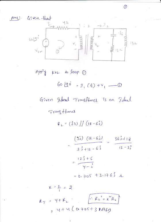
Consider the given ideal transformer circuit, where R-6 ? 1:2 -j6? 60/90° V rms (+ 12?
If 110 V rms is applied to the primary of an ideal transformer with a turns...
 If 110 V rms is applied to the primary of an ideal
transformer with a turns ratio of 500:1, what is the RMS voltage
output from the secondary? What is the peak voltage outpyt from the
secondary?
a. If 110 VAMS is applied to the primary of an ideal at is transformer with a turns ratio of 500:1, wh the RMS voltage output from the secondary? What is the peak voltage output from the secondary?
If 110 V rms is applied to the primary of an ideal
transformer with a turns ratio of 500:1, what is the RMS voltage
output from the secondary? What is the peak voltage outpyt from the
secondary?
a. If 110 VAMS is applied to the primary of an ideal at is transformer with a turns ratio of 500:1, wh the RMS voltage output from the secondary? What is the peak voltage output from the secondary?
roblem 5i Consider the circuit with an ideal transformer shown in Figure 5. 1:2 820 16...
 roblem 5i Consider the circuit with an ideal transformer shown in Figure 5. 1:2 820 16 ? V. 2 Figure 5. Ideal transformer circuit Submit the Following in the Online Quiz 20 points : Real and imaginary parts of l 12 1A 20 points: Real and imaginary parts of V, VV 5.a : Determine the numerical value of the phasor current 1, in rectangular form 5.b : Determine the numerical value of the phasor voltage 1z in rectangular form.
32. A transformer is to be designed to increase the 30 kV-rms output of a generator...
 32. A transformer is to be designed to increase the 30 kV-rms output of a generator to the transmission-line voltage of 345 kV-om. If the primary winding has 80 turns, how many turns must the secondary have? b. 70 c. 920 d. 9200 e 12 33. The primary winding of an electric train transformer has 400 turns and the Secondary has 50. If the input voltage is 120V(rms) what is the output voltage? a. 15 V (rms) b. 30 Vrms)...
Problem E1.2.6 (20 points) Consider the magntically coupled circuit that involves an ideal transformer as depicted...
 Problem E1.2.6 (20 points) Consider the magntically coupled circuit that involves an ideal transformer as depicted in Figure E1.2.6. The sinusoidal voltage source frequency is 20 x 103 (rad/sec). The load connected to the secondary winding (RHS of the ideal transformer) consists of a variable resistor R in series with a variable capacitor C. (a) Find the values of R and C for maximum power transfer from the voltage source in the primary winding. (b) What is the maximum average...
An inductor and a resistor are connected in series. When connected to a 60-Hz, 90-V (rms)...
An inductor and a resistor are connected in series. When connected to a 60-Hz, 90-V (rms) source, the voltage drop across the resistor is found to be 46 V (rms) and the power delivered to the circuit is 12 W. (a) Find the value of the resistance. Ω (b) Find the value of the inductance. H
Electrical Engineering Ideal Transformer Question 4. You are given the circuit shown below. Please note the...
 Electrical Engineering Ideal Transformer Question
4. You are given the circuit shown below. Please note the polarities of the currents and voltages at the ideal transformer. The source voltage is 10V RMS. 21 j11 1 1:4 j10N 400 W ell ell + + 1020 -j112 1 a) Write your voltage and current relationships for the transformer. b) Create a Thevenin equivalent circuit for everything to the left of the dashed line shown in the schematic. Provide the open circuit voltage...
Electrical Engineering Ideal Transformer Question
4. You are given the circuit shown below. Please note the polarities of the currents and voltages at the ideal transformer. The source voltage is 10V RMS. 21 j11 1 1:4 j10N 400 W ell ell + + 1020 -j112 1 a) Write your voltage and current relationships for the transformer. b) Create a Thevenin equivalent circuit for everything to the left of the dashed line shown in the schematic. Provide the open circuit voltage...
[5] (10 points) For the given circuit, V(t) = 7020 V rms, f = 60 Hz,...
 [5] (10 points) For the given circuit, V(t) = 7020 V rms, f = 60 Hz, R = 18 12, C = 50 uF, L = 0.001 H Find the following: (a) Power factor (b) Real Power (time average-power) L īs (c) Reactive Power (d) Complex power (e) Apparent power ww +21 Write your final ansers in the boxes.
1) What is the power outlet for an rms voltage of a standard 220 V? 2)...
1) What is the power outlet for an rms voltage of a standard 220 V? 2) Consider a driven RLC series AC circuit. At frequency f1 the capacitive reactance is twice the inductive reactance. Determine frequency f2 as a function of f1 so that the inductive reactance is twice the capacitive reactance. 3) A standard 120V ac source, connecting wires, and two ideal identical transformers are available. Each transformer has a different number of turns in the two coils. How...
Consider a RLC series circuit connected to a 220 V rms voltage source with a frequency...
Consider a RLC series circuit connected to a 220 V rms voltage source with a frequency of 120 Hz. WhatConsider a RLC series circuit connected to a 220 V rms voltage source with a frequency of 120 Hz. What is the peak current through the circuit if R = 250Ω, C = 90 μF, and L = 4.5 mH?is the peak current through the circuit if R = 250Ω, C = 90 μF, and L = 4.5 mH? A. 1.24...
In the circuit shown in the figure below, the ideal generator produces an rms voltage of...
 In the circuit shown in the
figure below, the ideal generator produces an rms voltage of 115 V
when operated at 60 Hz. What is the rms voltage between the
following points? Take R = 58 ohms, L = 129 mH, and C = 32 µF.
60 Hz
In the circuit shown in the
figure below, the ideal generator produces an rms voltage of 115 V
when operated at 60 Hz. What is the rms voltage between the
following points? Take R = 58 ohms, L = 129 mH, and C = 32 µF.
60 Hz
 If 110 V rms is applied to the primary of an ideal
transformer with a turns ratio of 500:1, what is the RMS voltage
output from the secondary? What is the peak voltage outpyt from the
secondary?
a. If 110 VAMS is applied to the primary of an ideal at is transformer with a turns ratio of 500:1, wh the RMS voltage output from the secondary? What is the peak voltage output from the secondary?
If 110 V rms is applied to the primary of an ideal
transformer with a turns ratio of 500:1, what is the RMS voltage
output from the secondary? What is the peak voltage outpyt from the
secondary?
a. If 110 VAMS is applied to the primary of an ideal at is transformer with a turns ratio of 500:1, wh the RMS voltage output from the secondary? What is the peak voltage output from the secondary?
 roblem 5i Consider the circuit with an ideal transformer shown in Figure 5. 1:2 820 16 ? V. 2 Figure 5. Ideal transformer circuit Submit the Following in the Online Quiz 20 points : Real and imaginary parts of l 12 1A 20 points: Real and imaginary parts of V, VV 5.a : Determine the numerical value of the phasor current 1, in rectangular form 5.b : Determine the numerical value of the phasor voltage 1z in rectangular form.
 32. A transformer is to be designed to increase the 30 kV-rms output of a generator to the transmission-line voltage of 345 kV-om. If the primary winding has 80 turns, how many turns must the secondary have? b. 70 c. 920 d. 9200 e 12 33. The primary winding of an electric train transformer has 400 turns and the Secondary has 50. If the input voltage is 120V(rms) what is the output voltage? a. 15 V (rms) b. 30 Vrms)...
 Problem E1.2.6 (20 points) Consider the magntically coupled circuit that involves an ideal transformer as depicted in Figure E1.2.6. The sinusoidal voltage source frequency is 20 x 103 (rad/sec). The load connected to the secondary winding (RHS of the ideal transformer) consists of a variable resistor R in series with a variable capacitor C. (a) Find the values of R and C for maximum power transfer from the voltage source in the primary winding. (b) What is the maximum average...
 Electrical Engineering Ideal Transformer Question
4. You are given the circuit shown below. Please note the polarities of the currents and voltages at the ideal transformer. The source voltage is 10V RMS. 21 j11 1 1:4 j10N 400 W ell ell + + 1020 -j112 1 a) Write your voltage and current relationships for the transformer. b) Create a Thevenin equivalent circuit for everything to the left of the dashed line shown in the schematic. Provide the open circuit voltage...
Electrical Engineering Ideal Transformer Question
4. You are given the circuit shown below. Please note the polarities of the currents and voltages at the ideal transformer. The source voltage is 10V RMS. 21 j11 1 1:4 j10N 400 W ell ell + + 1020 -j112 1 a) Write your voltage and current relationships for the transformer. b) Create a Thevenin equivalent circuit for everything to the left of the dashed line shown in the schematic. Provide the open circuit voltage...
 [5] (10 points) For the given circuit, V(t) = 7020 V rms, f = 60 Hz, R = 18 12, C = 50 uF, L = 0.001 H Find the following: (a) Power factor (b) Real Power (time average-power) L īs (c) Reactive Power (d) Complex power (e) Apparent power ww +21 Write your final ansers in the boxes.
 In the circuit shown in the
figure below, the ideal generator produces an rms voltage of 115 V
when operated at 60 Hz. What is the rms voltage between the
following points? Take R = 58 ohms, L = 129 mH, and C = 32 µF.
60 Hz
In the circuit shown in the
figure below, the ideal generator produces an rms voltage of 115 V
when operated at 60 Hz. What is the rms voltage between the
following points? Take R = 58 ohms, L = 129 mH, and C = 32 µF.
60 Hz
Most questions answered within 3 hours.
-
Where is the error in this code sequence?
String s1 = "Hello";
String s2 = "ello";...
asked 11 months ago -
Financial data for Joel de Paris, Inc., for last year
follow:
Joel de Paris, Inc.
Balance...
asked 11 months ago -
Consider this reaction:
Al2(SO4)3 (aq)+ BaCl3
(aq) Al2Cl6 (aq)- +
3BaSO4(s) . What is the...
asked 11 months ago -
Suppose that Savneet is considering increasing her
recent random sample from 20 car rentals to 40...
asked 11 months ago -
Trucks arrive at an unloading terminal at an average rate of 120
per hour.
Trucks arrive...
asked 11 months ago -
Why are methanol and ethanol completely soluble in water while
octanol is not very little soluble....
asked 11 months ago -
A facilities manager at a university reads in a research report
that the mean amount of...
asked 11 months ago -
When the CuSO4 is rehydrated by adding water to the anhydrous
compound, is this an endothermic...
asked 11 months ago -
A ray of sunlight is passing from diamond into crown glass; the
angle of incidence is...
asked 11 months ago -
A block of mass 0.249 kg is placed on top of a light, vertical
spring of...
asked 11 months ago -
how do the kidneys compensate in the presences of acidosis
a) trigger hyperventilate
b) reserve acid...
asked 11 months ago -
Question 501 pts
The rental rate of capital to the firm increases. Which of the
following...
asked 11 months ago