
Homework Answers

Add Answer to:
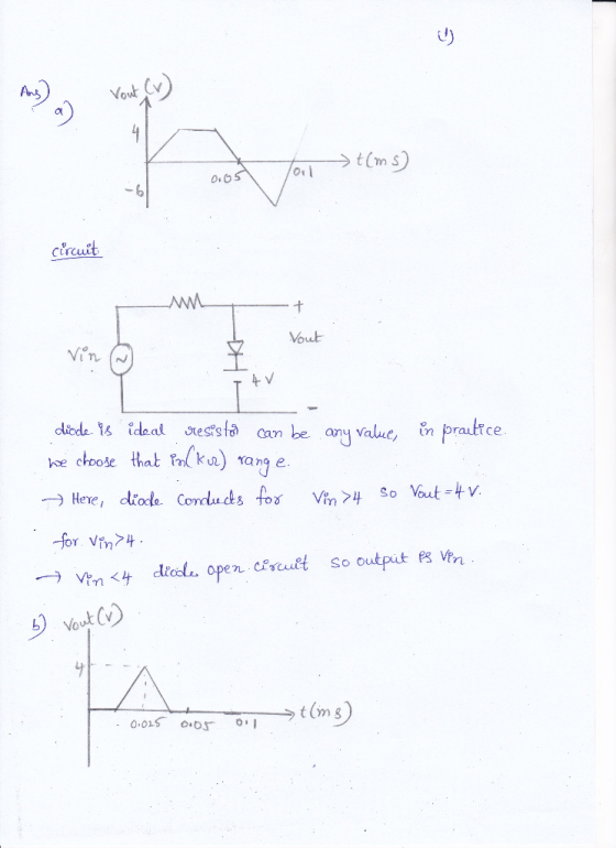
2. (30 points) Design circuits that can transform a 12 Vp-p, 10 kHz triangular input voltage...
24) For the three circuits (a), (b) and (c) shown below, the waveform of input voltage...
 24) For the three circuits (a), (b) and (c) shown below, the waveform of input voltage vy is given as shown below. For each circuit, sketch the waveform of output voltage vo for the given input voltage . Label the most positive and most negative output levels. Assume all diodes are ideal (vp- 0) and CR>> T. (10 points) +10 V-- -10 V TI ms (3 points) (b) o- (3 points) 3V (4 points) DH
BJT and Amplifier Circuits +15 V 27 k R2 680 Ω Compute: 53 1. Show the extra units and connections RE 680 2 R2 12 kC2 2. The input and the output impedance 3. The Voltage gain Av 4. If the input...
 BJT and Amplifier Circuits +15 V 27 k R2 680 Ω Compute: 53 1. Show the extra units and connections RE 680 2 R2 12 kC2 2. The input and the output impedance 3. The Voltage gain Av 4. If the input ac voltage with Vp-1 mV, draw the output voltage. What is the maximum vin value. 5. 6. The current gain Ai and Ap. 7. Compute the produced power and the consumed power in transistor and RL.
BJT and...
BJT and Amplifier Circuits +15 V 27 k R2 680 Ω Compute: 53 1. Show the extra units and connections RE 680 2 R2 12 kC2 2. The input and the output impedance 3. The Voltage gain Av 4. If the input ac voltage with Vp-1 mV, draw the output voltage. What is the maximum vin value. 5. 6. The current gain Ai and Ap. 7. Compute the produced power and the consumed power in transistor and RL.
BJT and...
Laboratory 1: operation amplifier characteristics A. Objectives: 1. To study the basic characteri...
 thanks
Laboratory 1: operation amplifier characteristics A. Objectives: 1. To study the basic characteristics of an operational amplifier 2. To study the bias circuit of an operational amplifier B. Apparatus: 1. DC Power supply 2. Experimental board and corresponding components 3. Electronic calculator (prepared by students) 4. Digital camera (prepared by students for photo taking of the experimental results) 5. Laptop computer with the software PicoScope 6 and Microsoft Word installed. 6. PicoScope PC Oscilloscope and its accessories. 7. Multimeter...
thanks
Laboratory 1: operation amplifier characteristics A. Objectives: 1. To study the basic characteristics of an operational amplifier 2. To study the bias circuit of an operational amplifier B. Apparatus: 1. DC Power supply 2. Experimental board and corresponding components 3. Electronic calculator (prepared by students) 4. Digital camera (prepared by students for photo taking of the experimental results) 5. Laptop computer with the software PicoScope 6 and Microsoft Word installed. 6. PicoScope PC Oscilloscope and its accessories. 7. Multimeter...
355 SERIES SINUSOIDAL CIRCUITS measared 000 10 mH 10 kHz R E-8V (P-p) Va 1 kn...
 355 SERIES SINUSOIDAL CIRCUITS measared 000 10 mH 10 kHz R E-8V (P-p) Va 1 kn Channel 2 Vert: 1 Vidiv. Har: 20 μεiv . Channel I 1 Vidiv Vert Hoc : 20 μdiv. FIG. 9.1 After setting E to 8 V (p-p), determine the peak-to-peak voltage for Ve from chan- (b) nel 2 and record in the top row of Table 9.1. (c) Determine the phase angle e, between E and Vg using the connections shown in Fig. 9.1...
I need help with numbers 4,6,7,8,9 please? 12 VDC 1.0 k ohms 10k ohms C3 1.0 uF C1 1.0 UF , R Load Baca 1 80 10k ohns 300 mVp-p 1.0 kHz 100 ohms .7k ohms C2 47uF 330 ohms 4. Calculate the following pa...
 I need help with numbers 4,6,7,8,9 please?
12 VDC 1.0 k ohms 10k ohms C3 1.0 uF C1 1.0 UF , R Load Baca 1 80 10k ohns 300 mVp-p 1.0 kHz 100 ohms .7k ohms C2 47uF 330 ohms 4. Calculate the following parameters assuming capacitor C2 has been removed from the circuit with the 1.0k2 resistor as the load. RIN BASE Av Vour 5. Construct the circuit shown on the previous page. Before connecting the AC supply, measure...
I need help with numbers 4,6,7,8,9 please?
12 VDC 1.0 k ohms 10k ohms C3 1.0 uF C1 1.0 UF , R Load Baca 1 80 10k ohns 300 mVp-p 1.0 kHz 100 ohms .7k ohms C2 47uF 330 ohms 4. Calculate the following parameters assuming capacitor C2 has been removed from the circuit with the 1.0k2 resistor as the load. RIN BASE Av Vour 5. Construct the circuit shown on the previous page. Before connecting the AC supply, measure...
QUESTION 3 (a) If the Fourier transform of (t) is X(c) = 12 (a+2)j@+6) determine the...
 QUESTION 3 (a) If the Fourier transform of (t) is X(c) = 12 (a+2)j@+6) determine the transform for (-21-1). [5 marks] (b) Based on Figure Q3(b), give the expression for signal xt) in unit step function. From your obtained expression, find the Fourier transform of x(). Then compare your answer using the formula of Fourier transform. x() 10 0 Figure Q3(b) [9 marks] 다. For the linear system in Figure Q3(e), when the input voltage is vr(t) = 2sgn(t) V....
help please! And can you explain me how you did it? 1. The current and voltage...
 help please! And can you explain me how you did it?
1. The current and voltage for an element are shown below (assume+ for the passive sign convention) a. b. Draw a plot of power for that elemen Find the total energy delivered to the element in 0 to 60 ms. t on the axes provided. [15 pts.] i (mA) 250 10 20 40 50 60 70 (ms) -250 v (V) t (ms) 20 40 50 60 70 p (W)...
help please! And can you explain me how you did it?
1. The current and voltage for an element are shown below (assume+ for the passive sign convention) a. b. Draw a plot of power for that elemen Find the total energy delivered to the element in 0 to 60 ms. t on the axes provided. [15 pts.] i (mA) 250 10 20 40 50 60 70 (ms) -250 v (V) t (ms) 20 40 50 60 70 p (W)...
EXPERIMENT 11 STEP RESPONSE TO RC AND RL CIRCUITS pages 11-4 thru 11-7. tep response of the RC an...
 EXPERIMENT 11 STEP RESPONSE TO RC AND RL CIRCUITS pages 11-4 thru 11-7. tep response of the RC and RL circuits is included in OBJECTIVE: O analyze the voltage and current characteristics of a Resistance - Capacitance (RC) circuit when driven by a step voltage function. To analyze the voltage and current characteristics of a Resistance- Inductor (RL) circuit when driven by a step voltage function To design an RC circuit to yield a specified output voltage with a step...
10 32. Find the equivalent resistance between the points X and Y for the circuits shown...
 10 32. Find the equivalent resistance between the points X and Y for the circuits shown below. [Ans:6.30) mm 12 125 12 33. Find the currents l,l213 in the following circuit, by using Delta to Star or Star to Delta Transformation. [Ans:0.87A, -2.29A, 1.42A) 13 n 30 v 200 6 15 V 15 105 Page
a9a resistive load. Inductor 3-(35 pts) Design a converter that has an input voltage of 24 V DC and supplies 18 V DC to current is desired to be continuous and must not change more than 30 % of i...
 a9a resistive load. Inductor 3-(35 pts) Design a converter that has an input voltage of 24 V DC and supplies 18 V DC to current is desired to be continuous and must not change more than 30 % of its average value voltage ripple must be lower than 2 %. Switching frequency is 10 kHz. a) Draw the circuit diagram. Calculate the duty ratio. Calculate values for 2 desired conditions of the inductor current and determine the value of the...
 24) For the three circuits (a), (b) and (c) shown below, the waveform of input voltage vy is given as shown below. For each circuit, sketch the waveform of output voltage vo for the given input voltage . Label the most positive and most negative output levels. Assume all diodes are ideal (vp- 0) and CR>> T. (10 points) +10 V-- -10 V TI ms (3 points) (b) o- (3 points) 3V (4 points) DH
 BJT and Amplifier Circuits +15 V 27 k R2 680 Ω Compute: 53 1. Show the extra units and connections RE 680 2 R2 12 kC2 2. The input and the output impedance 3. The Voltage gain Av 4. If the input ac voltage with Vp-1 mV, draw the output voltage. What is the maximum vin value. 5. 6. The current gain Ai and Ap. 7. Compute the produced power and the consumed power in transistor and RL.
BJT and...
BJT and Amplifier Circuits +15 V 27 k R2 680 Ω Compute: 53 1. Show the extra units and connections RE 680 2 R2 12 kC2 2. The input and the output impedance 3. The Voltage gain Av 4. If the input ac voltage with Vp-1 mV, draw the output voltage. What is the maximum vin value. 5. 6. The current gain Ai and Ap. 7. Compute the produced power and the consumed power in transistor and RL.
BJT and...
 thanks
Laboratory 1: operation amplifier characteristics A. Objectives: 1. To study the basic characteristics of an operational amplifier 2. To study the bias circuit of an operational amplifier B. Apparatus: 1. DC Power supply 2. Experimental board and corresponding components 3. Electronic calculator (prepared by students) 4. Digital camera (prepared by students for photo taking of the experimental results) 5. Laptop computer with the software PicoScope 6 and Microsoft Word installed. 6. PicoScope PC Oscilloscope and its accessories. 7. Multimeter...
thanks
Laboratory 1: operation amplifier characteristics A. Objectives: 1. To study the basic characteristics of an operational amplifier 2. To study the bias circuit of an operational amplifier B. Apparatus: 1. DC Power supply 2. Experimental board and corresponding components 3. Electronic calculator (prepared by students) 4. Digital camera (prepared by students for photo taking of the experimental results) 5. Laptop computer with the software PicoScope 6 and Microsoft Word installed. 6. PicoScope PC Oscilloscope and its accessories. 7. Multimeter...
 355 SERIES SINUSOIDAL CIRCUITS measared 000 10 mH 10 kHz R E-8V (P-p) Va 1 kn Channel 2 Vert: 1 Vidiv. Har: 20 μεiv . Channel I 1 Vidiv Vert Hoc : 20 μdiv. FIG. 9.1 After setting E to 8 V (p-p), determine the peak-to-peak voltage for Ve from chan- (b) nel 2 and record in the top row of Table 9.1. (c) Determine the phase angle e, between E and Vg using the connections shown in Fig. 9.1...
 I need help with numbers 4,6,7,8,9 please?
12 VDC 1.0 k ohms 10k ohms C3 1.0 uF C1 1.0 UF , R Load Baca 1 80 10k ohns 300 mVp-p 1.0 kHz 100 ohms .7k ohms C2 47uF 330 ohms 4. Calculate the following parameters assuming capacitor C2 has been removed from the circuit with the 1.0k2 resistor as the load. RIN BASE Av Vour 5. Construct the circuit shown on the previous page. Before connecting the AC supply, measure...
I need help with numbers 4,6,7,8,9 please?
12 VDC 1.0 k ohms 10k ohms C3 1.0 uF C1 1.0 UF , R Load Baca 1 80 10k ohns 300 mVp-p 1.0 kHz 100 ohms .7k ohms C2 47uF 330 ohms 4. Calculate the following parameters assuming capacitor C2 has been removed from the circuit with the 1.0k2 resistor as the load. RIN BASE Av Vour 5. Construct the circuit shown on the previous page. Before connecting the AC supply, measure...
 QUESTION 3 (a) If the Fourier transform of (t) is X(c) = 12 (a+2)j@+6) determine the transform for (-21-1). [5 marks] (b) Based on Figure Q3(b), give the expression for signal xt) in unit step function. From your obtained expression, find the Fourier transform of x(). Then compare your answer using the formula of Fourier transform. x() 10 0 Figure Q3(b) [9 marks] 다. For the linear system in Figure Q3(e), when the input voltage is vr(t) = 2sgn(t) V....
 help please! And can you explain me how you did it?
1. The current and voltage for an element are shown below (assume+ for the passive sign convention) a. b. Draw a plot of power for that elemen Find the total energy delivered to the element in 0 to 60 ms. t on the axes provided. [15 pts.] i (mA) 250 10 20 40 50 60 70 (ms) -250 v (V) t (ms) 20 40 50 60 70 p (W)...
help please! And can you explain me how you did it?
1. The current and voltage for an element are shown below (assume+ for the passive sign convention) a. b. Draw a plot of power for that elemen Find the total energy delivered to the element in 0 to 60 ms. t on the axes provided. [15 pts.] i (mA) 250 10 20 40 50 60 70 (ms) -250 v (V) t (ms) 20 40 50 60 70 p (W)...
 EXPERIMENT 11 STEP RESPONSE TO RC AND RL CIRCUITS pages 11-4 thru 11-7. tep response of the RC and RL circuits is included in OBJECTIVE: O analyze the voltage and current characteristics of a Resistance - Capacitance (RC) circuit when driven by a step voltage function. To analyze the voltage and current characteristics of a Resistance- Inductor (RL) circuit when driven by a step voltage function To design an RC circuit to yield a specified output voltage with a step...
 10 32. Find the equivalent resistance between the points X and Y for the circuits shown below. [Ans:6.30) mm 12 125 12 33. Find the currents l,l213 in the following circuit, by using Delta to Star or Star to Delta Transformation. [Ans:0.87A, -2.29A, 1.42A) 13 n 30 v 200 6 15 V 15 105 Page
 a9a resistive load. Inductor 3-(35 pts) Design a converter that has an input voltage of 24 V DC and supplies 18 V DC to current is desired to be continuous and must not change more than 30 % of its average value voltage ripple must be lower than 2 %. Switching frequency is 10 kHz. a) Draw the circuit diagram. Calculate the duty ratio. Calculate values for 2 desired conditions of the inductor current and determine the value of the...
Most questions answered within 3 hours.
-
Where is the error in this code sequence?
String s1 = "Hello";
String s2 = "ello";...
asked 10 months ago -
Financial data for Joel de Paris, Inc., for last year
follow:
Joel de Paris, Inc.
Balance...
asked 10 months ago -
Consider this reaction:
Al2(SO4)3 (aq)+ BaCl3
(aq) Al2Cl6 (aq)- +
3BaSO4(s) . What is the...
asked 10 months ago -
Suppose that Savneet is considering increasing her
recent random sample from 20 car rentals to 40...
asked 10 months ago -
Trucks arrive at an unloading terminal at an average rate of 120
per hour.
Trucks arrive...
asked 10 months ago -
Why are methanol and ethanol completely soluble in water while
octanol is not very little soluble....
asked 10 months ago -
A facilities manager at a university reads in a research report
that the mean amount of...
asked 10 months ago -
When the CuSO4 is rehydrated by adding water to the anhydrous
compound, is this an endothermic...
asked 10 months ago -
A ray of sunlight is passing from diamond into crown glass; the
angle of incidence is...
asked 10 months ago -
A block of mass 0.249 kg is placed on top of a light, vertical
spring of...
asked 10 months ago -
how do the kidneys compensate in the presences of acidosis
a) trigger hyperventilate
b) reserve acid...
asked 10 months ago -
Question 501 pts
The rental rate of capital to the firm increases. Which of the
following...
asked 10 months ago