
Homework Answers
Please fin the attachment for the solution 


Add Answer to:
N is 1
QUESTION 2 For the bar assemblage shown Data: in the figure, determine the...
For the bar assemblage shown Data: in the figure, determine the nodal displacements, the E=nx10" Pa...
 For the bar assemblage shown Data: in the figure, determine the nodal displacements, the E=nx10" Pa forces in each element, the L; =nx 500mm A=nx10-m? 13 reactions and the stresses L =nx 500mm F =nx10*N L = n x 250mm F2 = 2.5x F, F2 12 L
structural analysis Figure Q() Question 2 For the bar assemblages shown in Figure Q(2), determine the nodal displacements, the forces in each element and the reactions. Use the direct stiffness me...
 structural analysis
Figure Q() Question 2 For the bar assemblages shown in Figure Q(2), determine the nodal displacements, the forces in each element and the reactions. Use the direct stiffness method (25 marks) 35 kN E-210 GPa 2 A4 x 10m2 1 m im
Figure Q() Question 2 For the bar assemblages shown in Figure Q(2), determine the nodal displacements, the forces in each element and the reactions. Use the direct stiffness method (25 marks) 35 kN E-210 GPa 2...
structural analysis
Figure Q() Question 2 For the bar assemblages shown in Figure Q(2), determine the nodal displacements, the forces in each element and the reactions. Use the direct stiffness method (25 marks) 35 kN E-210 GPa 2 A4 x 10m2 1 m im
Figure Q() Question 2 For the bar assemblages shown in Figure Q(2), determine the nodal displacements, the forces in each element and the reactions. Use the direct stiffness method (25 marks) 35 kN E-210 GPa 2...
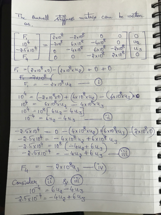
a. Compute the total stiffness matrix [K] of the assemblage shown in Figure 3-1 by superimposing...
 a. Compute the total stiffness matrix [K] of the assemblage shown in Figure 3-1 by superimposing the stiffness matrices of the individual bars. Note that should be in terms of A. As, A, E, E E, L. and L. Here A, E, and are generic symbols used for cross-sectional area modulus of elasticity, and length, respectively Figure P3-1 Now let As - Ag-A-A.E E, E E and L-L L -L nodes 1 and 4 are fixed and a force Pacts...
Problem 2: a. For the plane truss shown in Figure 2, determine the nodal displacements, the element forces and stresses, and the support reactions. All elements have E-70 GPa and A-25 cm 100 k...
 Problem 2: a. For the plane truss shown in Figure 2, determine the nodal displacements, the element forces and stresses, and the support reactions. All elements have E-70 GPa and A-25 cm 100 kN 50 kN 50 kN 4 4 6 Figure 2. Plane Truss
Problem 2: a. For the plane truss shown in Figure 2, determine the nodal displacements, the element forces and stresses, and the support reactions. All elements have E-70 GPa and A-25 cm 100 kN 50...
Problem 2: a. For the plane truss shown in Figure 2, determine the nodal displacements, the element forces and stresses, and the support reactions. All elements have E-70 GPa and A-25 cm 100 kN 50 kN 50 kN 4 4 6 Figure 2. Plane Truss
Problem 2: a. For the plane truss shown in Figure 2, determine the nodal displacements, the element forces and stresses, and the support reactions. All elements have E-70 GPa and A-25 cm 100 kN 50...
For the spring assemblage shown in Figure 2-13, obtain (a) the global stiffness matrix, (b) the displacements of nodes 2-4, (c) the global nodal forces, and (d) the local element forces.
For the spring assemblage shown in Figure 2-13, obtain (a) the global stiffness matrix, (b) the displacements of nodes 2-4, (c) the global nodal forces, and (d) the local element forces. Node l is fixed while node 5 is given a fixed, known displacement δ= 20.0 mm. The spring constants are all equal to k = 200 kN/m.
Consider the bar in Fig.3.7 loaded as shown. Determine the nodal displacements, element stresses, and support...
 Consider the bar in Fig.3.7 loaded as shown. Determine the nodal displacements, element stresses, and support reactions. Solve this problem by hand calculation, adopting the elim- ination method for handling boundary conditions. Verify your results using program FEMID. 400 mm2 250 mm2 P-300 kN > X
Consider the bar in Fig.3.7 loaded as shown. Determine the nodal displacements, element stresses, and support reactions. Solve this problem by hand calculation, adopting the elim- ination method for handling boundary conditions. Verify your...
Consider the bar in Fig.3.7 loaded as shown. Determine the nodal displacements, element stresses, and support reactions. Solve this problem by hand calculation, adopting the elim- ination method for handling boundary conditions. Verify your results using program FEMID. 400 mm2 250 mm2 P-300 kN > X
Consider the bar in Fig.3.7 loaded as shown. Determine the nodal displacements, element stresses, and support reactions. Solve this problem by hand calculation, adopting the elim- ination method for handling boundary conditions. Verify your...
Problem 2: For the beam shown in below figure, determine the nodal displacements and slopes, the...
 Problem 2: For the beam shown in below figure, determine the nodal displacements and slopes, the forces in each element, and the reactions. 4 kN/ Im E 70 GPa 13 x 10-4 m4 4 m
Determine the nodal displacements and reaction forces using the finite element direct method for the 1-D bar elements connected as shown below.
 Determine the nodal displacements and reaction forces using the finite element direct method for the 1-D bar elements connected as shown below. Do not rename the nodes or elements when solving. Assume that the bars can only undergo translation in x (1 DOF at each node). Nodes 1 and 3 are fixed Element 1 has Young's Modulus of 300 Pa, length of 1 m and cross-sectional area of 1 m2. Element 2 has Young's Modulus of 200 Pa, length of 2...
For the bar subjected to axial load shown in Figure 1 to 2, determine the nodal...
 For the bar subjected to axial load shown in Figure 1 to 2, determine the nodal displacements and Reaction Force. Let Area = 2in^2, E= 30E6 psi = p(x) 300 lb/in 2 3 30 in 60 in x Figure 1 P(x) = 10x lb/in 2 3 30 in 60 in Figure 2.
3.24 Determine the nodal displacements and the element forces for the truss shown in Figure P3-24. Assume all elements have the same AE 4 15 m 4 2 20 m Figure P3-24 3.24 Determine the nodal...
 3.24 Determine the nodal displacements and the element forces for the truss shown in Figure P3-24. Assume all elements have the same AE 4 15 m 4 2 20 m Figure P3-24
3.24 Determine the nodal displacements and the element forces for the truss shown in Figure P3-24. Assume all elements have the same AE
4 15 m 4 2 20 m Figure P3-24
3.24 Determine the nodal displacements and the element forces for the truss shown in Figure P3-24. Assume all elements have the same AE 4 15 m 4 2 20 m Figure P3-24
3.24 Determine the nodal displacements and the element forces for the truss shown in Figure P3-24. Assume all elements have the same AE
4 15 m 4 2 20 m Figure P3-24
 For the bar assemblage shown Data: in the figure, determine the nodal displacements, the E=nx10" Pa forces in each element, the L; =nx 500mm A=nx10-m? 13 reactions and the stresses L =nx 500mm F =nx10*N L = n x 250mm F2 = 2.5x F, F2 12 L
 structural analysis
Figure Q() Question 2 For the bar assemblages shown in Figure Q(2), determine the nodal displacements, the forces in each element and the reactions. Use the direct stiffness method (25 marks) 35 kN E-210 GPa 2 A4 x 10m2 1 m im
Figure Q() Question 2 For the bar assemblages shown in Figure Q(2), determine the nodal displacements, the forces in each element and the reactions. Use the direct stiffness method (25 marks) 35 kN E-210 GPa 2...
structural analysis
Figure Q() Question 2 For the bar assemblages shown in Figure Q(2), determine the nodal displacements, the forces in each element and the reactions. Use the direct stiffness method (25 marks) 35 kN E-210 GPa 2 A4 x 10m2 1 m im
Figure Q() Question 2 For the bar assemblages shown in Figure Q(2), determine the nodal displacements, the forces in each element and the reactions. Use the direct stiffness method (25 marks) 35 kN E-210 GPa 2...
 a. Compute the total stiffness matrix [K] of the assemblage shown in Figure 3-1 by superimposing the stiffness matrices of the individual bars. Note that should be in terms of A. As, A, E, E E, L. and L. Here A, E, and are generic symbols used for cross-sectional area modulus of elasticity, and length, respectively Figure P3-1 Now let As - Ag-A-A.E E, E E and L-L L -L nodes 1 and 4 are fixed and a force Pacts...
 Problem 2: a. For the plane truss shown in Figure 2, determine the nodal displacements, the element forces and stresses, and the support reactions. All elements have E-70 GPa and A-25 cm 100 kN 50 kN 50 kN 4 4 6 Figure 2. Plane Truss
Problem 2: a. For the plane truss shown in Figure 2, determine the nodal displacements, the element forces and stresses, and the support reactions. All elements have E-70 GPa and A-25 cm 100 kN 50...
Problem 2: a. For the plane truss shown in Figure 2, determine the nodal displacements, the element forces and stresses, and the support reactions. All elements have E-70 GPa and A-25 cm 100 kN 50 kN 50 kN 4 4 6 Figure 2. Plane Truss
Problem 2: a. For the plane truss shown in Figure 2, determine the nodal displacements, the element forces and stresses, and the support reactions. All elements have E-70 GPa and A-25 cm 100 kN 50...
 Consider the bar in Fig.3.7 loaded as shown. Determine the nodal displacements, element stresses, and support reactions. Solve this problem by hand calculation, adopting the elim- ination method for handling boundary conditions. Verify your results using program FEMID. 400 mm2 250 mm2 P-300 kN > X
Consider the bar in Fig.3.7 loaded as shown. Determine the nodal displacements, element stresses, and support reactions. Solve this problem by hand calculation, adopting the elim- ination method for handling boundary conditions. Verify your...
Consider the bar in Fig.3.7 loaded as shown. Determine the nodal displacements, element stresses, and support reactions. Solve this problem by hand calculation, adopting the elim- ination method for handling boundary conditions. Verify your results using program FEMID. 400 mm2 250 mm2 P-300 kN > X
Consider the bar in Fig.3.7 loaded as shown. Determine the nodal displacements, element stresses, and support reactions. Solve this problem by hand calculation, adopting the elim- ination method for handling boundary conditions. Verify your...
 Problem 2: For the beam shown in below figure, determine the nodal displacements and slopes, the forces in each element, and the reactions. 4 kN/ Im E 70 GPa 13 x 10-4 m4 4 m
 Determine the nodal displacements and reaction forces using the finite element direct method for the 1-D bar elements connected as shown below. Do not rename the nodes or elements when solving. Assume that the bars can only undergo translation in x (1 DOF at each node). Nodes 1 and 3 are fixed Element 1 has Young's Modulus of 300 Pa, length of 1 m and cross-sectional area of 1 m2. Element 2 has Young's Modulus of 200 Pa, length of 2...
 For the bar subjected to axial load shown in Figure 1 to 2, determine the nodal displacements and Reaction Force. Let Area = 2in^2, E= 30E6 psi = p(x) 300 lb/in 2 3 30 in 60 in x Figure 1 P(x) = 10x lb/in 2 3 30 in 60 in Figure 2.
 3.24 Determine the nodal displacements and the element forces for the truss shown in Figure P3-24. Assume all elements have the same AE 4 15 m 4 2 20 m Figure P3-24
3.24 Determine the nodal displacements and the element forces for the truss shown in Figure P3-24. Assume all elements have the same AE
4 15 m 4 2 20 m Figure P3-24
3.24 Determine the nodal displacements and the element forces for the truss shown in Figure P3-24. Assume all elements have the same AE 4 15 m 4 2 20 m Figure P3-24
3.24 Determine the nodal displacements and the element forces for the truss shown in Figure P3-24. Assume all elements have the same AE
4 15 m 4 2 20 m Figure P3-24
Most questions answered within 3 hours.
-
Where is the error in this code sequence?
String s1 = "Hello";
String s2 = "ello";...
asked 10 months ago -
Financial data for Joel de Paris, Inc., for last year
follow:
Joel de Paris, Inc.
Balance...
asked 10 months ago -
Consider this reaction:
Al2(SO4)3 (aq)+ BaCl3
(aq) Al2Cl6 (aq)- +
3BaSO4(s) . What is the...
asked 10 months ago -
Suppose that Savneet is considering increasing her
recent random sample from 20 car rentals to 40...
asked 10 months ago -
Trucks arrive at an unloading terminal at an average rate of 120
per hour.
Trucks arrive...
asked 10 months ago -
Why are methanol and ethanol completely soluble in water while
octanol is not very little soluble....
asked 10 months ago -
A facilities manager at a university reads in a research report
that the mean amount of...
asked 10 months ago -
When the CuSO4 is rehydrated by adding water to the anhydrous
compound, is this an endothermic...
asked 10 months ago -
A ray of sunlight is passing from diamond into crown glass; the
angle of incidence is...
asked 10 months ago -
A block of mass 0.249 kg is placed on top of a light, vertical
spring of...
asked 10 months ago -
how do the kidneys compensate in the presences of acidosis
a) trigger hyperventilate
b) reserve acid...
asked 10 months ago -
Question 501 pts
The rental rate of capital to the firm increases. Which of the
following...
asked 10 months ago