Control systems: for the op-amp circuit we have R = 100k, C = 20uF. Find the transfer function between the inputs V1, V2, and the output V3.
***note: answer provided, please show work.

ANS: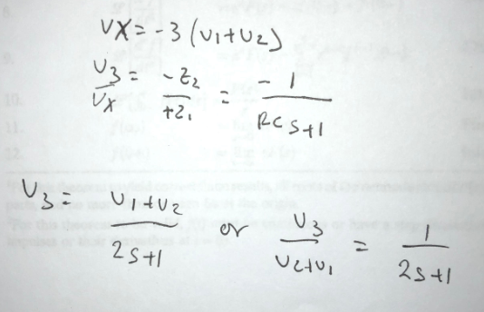
Homework Answers

![:. 43=-1 V 1+25 V = (3[vk.)) [tmez 0 ] 1+as :V2 = (V, tve) tas ItzS con V = S T+2S (V, Val](http://img.homeworklib.com/questions/7f5d2db0-1518-11ec-8f9f-8fe74edeb530.png?x-oss-process=image/resize,w_560)
Please give ? if u understood the steps.

Add Answer to:
Control systems: for the op-amp circuit we have R = 100k, C =
20uF. Find the...
Assuming an ideal op-amp in the following circuit, find output voltage, Vo if R1= 2 KS,...
 Assuming an ideal op-amp in the following circuit, find output voltage, Vo if R1= 2 KS, R2=8 KN, R3=3.4 KA, R4=6 KN, R5=20 KN, R6=2.9 KN, RL=12.5 KN, V1=1V, 12=0.5 mA and V3=3.1 V. R6 R1 R5 VO + RL 12 R2 V1 R3 { R4 w V3 Answer: "V
Assuming an ideal op-amp in the following circuit, find output voltage, Vo if R1= 2 K2,...
 Assuming an ideal op-amp in the following circuit, find output voltage, Vo if R1= 2 K2, R2=8 K12, R3=3.8 KS2, R4=6 KI2, R5=15 KS2, R6=3.8 KN, RL=9.8 K12, V1=1V, 12=0.5 mA and V3=2.2 V. } R6 R1 w R5 w + Vo + } RL 12 R2 V1 R3 R4 + +1 V3 Using the above circuit, but consider the following component values: R1= 2 KN R2=8 K2, R3=4.1 K12, R4=6 KI2, R5=17.0 K12, R6=15 KI, RL=10 KI, V1=1V, 12=0.5mA...
Assuming an ideal op-amp in the following circuit, find output voltage, Vo if R1= 2 K2,...
 Assuming an ideal op-amp in the following circuit, find output voltage, Vo if R1= 2 K2, R2=8 K2, R3=5.1 K2, R4=6 KN, R5=14 KN, R6=4.2 KS, RL=10.3 KS, V1=1V, 12=0.5 mA and V3=3.2 V. R6 R1 R5 Vo w + * RL + 12 R2 V1 R3 R4 V3 Answer: OV Using the above circuit, but consider the following component values: R1= 2 K12 R2=8 K2, R3=2.9 K2, R4=6 KI2, R5=10.8 K92, R6=15 KO, RL=10 K2, V1=1V, 12=0.5mA and V3=2V....
(c) (d) 7. Howland current source. [7 pts. The op-amp circuit shown is a Howland current source or current pump. R, at loadn provided that 3 R R2 R Show that os n provided that Note: despite the appa...
 (c) (d) 7. Howland current source. [7 pts. The op-amp circuit shown is a Howland current source or current pump. R, at loadn provided that 3 R R2 R Show that os n provided that Note: despite the apparent cleverness of this current source, several issues preclude its widespread application, e.g., the resistors must be exactly matched or the circuit deviates from the result derived above. Additionally, performance is limited by the common-mode rejection ratio of the op-amp, the resistors...
Vout should be a sinusoid signal of 12Vp-p Dc voltage to uA741 : +/-8.5V Please simulate...
 Vout should be a sinusoid signal of 12Vp-p
Dc voltage to uA741 : +/-8.5V
Please simulate as well
please help, im completely lost on this
this is all of the information
Experiment 5. RC Sinusoidal Oscillators PURPOSE: This laboratory provides an introduction to the background, analysis and design of sinusoidal oscillators using RC feedback networks and active devices to achieve the criteria for continuous oscillations to occur. EQUIPMENT REQUIRED : 1 Operational amplifier u.A741 1 CEU development station Resistors and...
Vout should be a sinusoid signal of 12Vp-p
Dc voltage to uA741 : +/-8.5V
Please simulate as well
please help, im completely lost on this
this is all of the information
Experiment 5. RC Sinusoidal Oscillators PURPOSE: This laboratory provides an introduction to the background, analysis and design of sinusoidal oscillators using RC feedback networks and active devices to achieve the criteria for continuous oscillations to occur. EQUIPMENT REQUIRED : 1 Operational amplifier u.A741 1 CEU development station Resistors and...
 Assuming an ideal op-amp in the following circuit, find output voltage, Vo if R1= 2 KS, R2=8 KN, R3=3.4 KA, R4=6 KN, R5=20 KN, R6=2.9 KN, RL=12.5 KN, V1=1V, 12=0.5 mA and V3=3.1 V. R6 R1 R5 VO + RL 12 R2 V1 R3 { R4 w V3 Answer: "V
 Assuming an ideal op-amp in the following circuit, find output voltage, Vo if R1= 2 K2, R2=8 K12, R3=3.8 KS2, R4=6 KI2, R5=15 KS2, R6=3.8 KN, RL=9.8 K12, V1=1V, 12=0.5 mA and V3=2.2 V. } R6 R1 w R5 w + Vo + } RL 12 R2 V1 R3 R4 + +1 V3 Using the above circuit, but consider the following component values: R1= 2 KN R2=8 K2, R3=4.1 K12, R4=6 KI2, R5=17.0 K12, R6=15 KI, RL=10 KI, V1=1V, 12=0.5mA...
 Assuming an ideal op-amp in the following circuit, find output voltage, Vo if R1= 2 K2, R2=8 K2, R3=5.1 K2, R4=6 KN, R5=14 KN, R6=4.2 KS, RL=10.3 KS, V1=1V, 12=0.5 mA and V3=3.2 V. R6 R1 R5 Vo w + * RL + 12 R2 V1 R3 R4 V3 Answer: OV Using the above circuit, but consider the following component values: R1= 2 K12 R2=8 K2, R3=2.9 K2, R4=6 KI2, R5=10.8 K92, R6=15 KO, RL=10 K2, V1=1V, 12=0.5mA and V3=2V....
 (c) (d) 7. Howland current source. [7 pts. The op-amp circuit shown is a Howland current source or current pump. R, at loadn provided that 3 R R2 R Show that os n provided that Note: despite the apparent cleverness of this current source, several issues preclude its widespread application, e.g., the resistors must be exactly matched or the circuit deviates from the result derived above. Additionally, performance is limited by the common-mode rejection ratio of the op-amp, the resistors...
 Vout should be a sinusoid signal of 12Vp-p
Dc voltage to uA741 : +/-8.5V
Please simulate as well
please help, im completely lost on this
this is all of the information
Experiment 5. RC Sinusoidal Oscillators PURPOSE: This laboratory provides an introduction to the background, analysis and design of sinusoidal oscillators using RC feedback networks and active devices to achieve the criteria for continuous oscillations to occur. EQUIPMENT REQUIRED : 1 Operational amplifier u.A741 1 CEU development station Resistors and...
Vout should be a sinusoid signal of 12Vp-p
Dc voltage to uA741 : +/-8.5V
Please simulate as well
please help, im completely lost on this
this is all of the information
Experiment 5. RC Sinusoidal Oscillators PURPOSE: This laboratory provides an introduction to the background, analysis and design of sinusoidal oscillators using RC feedback networks and active devices to achieve the criteria for continuous oscillations to occur. EQUIPMENT REQUIRED : 1 Operational amplifier u.A741 1 CEU development station Resistors and...
Most questions answered within 3 hours.
-
Where is the error in this code sequence?
String s1 = "Hello";
String s2 = "ello";...
asked 10 months ago -
Financial data for Joel de Paris, Inc., for last year
follow:
Joel de Paris, Inc.
Balance...
asked 10 months ago -
Consider this reaction:
Al2(SO4)3 (aq)+ BaCl3
(aq) Al2Cl6 (aq)- +
3BaSO4(s) . What is the...
asked 10 months ago -
Suppose that Savneet is considering increasing her
recent random sample from 20 car rentals to 40...
asked 10 months ago -
Trucks arrive at an unloading terminal at an average rate of 120
per hour.
Trucks arrive...
asked 10 months ago -
Why are methanol and ethanol completely soluble in water while
octanol is not very little soluble....
asked 10 months ago -
A facilities manager at a university reads in a research report
that the mean amount of...
asked 10 months ago -
When the CuSO4 is rehydrated by adding water to the anhydrous
compound, is this an endothermic...
asked 10 months ago -
A ray of sunlight is passing from diamond into crown glass; the
angle of incidence is...
asked 10 months ago -
A block of mass 0.249 kg is placed on top of a light, vertical
spring of...
asked 10 months ago -
how do the kidneys compensate in the presences of acidosis
a) trigger hyperventilate
b) reserve acid...
asked 10 months ago -
Question 501 pts
The rental rate of capital to the firm increases. Which of the
following...
asked 10 months ago