
Homework Answers
Add Answer to:
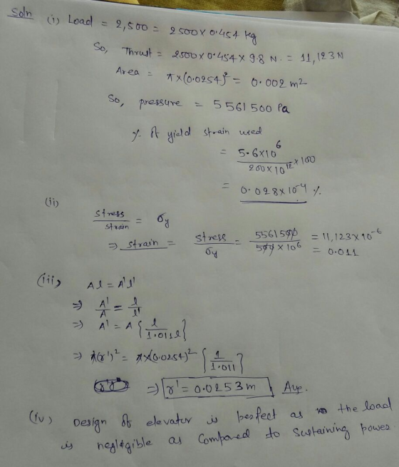
The capacity of a passenger elevator is 2, 500 pounds. This load is supported by a...
The shaft in the figure below is supported on journal bearings that do not offer any resistance t...
 The shaft in the figure below is supported on journal bearings that do not offer any resistance to axial load. The yield strength of the material is o",-300 MPa and the safety factor is FS-2.5 Derive an expression for the components of the stress tensor at a cross section of the shaft Neglect the shear stress due to the transverse shear forces and determine to the nearest millimeter, the smallest diameter of the shaft that will support the loading strength....
The shaft in the figure below is supported on journal bearings that do not offer any resistance t...
 The shaft in the figure below is supported on journal bearings that do not offer any resistance to axial load. The yield strength of the material is Ơ,-300 MPa and the safety factor is FS-2.5 1) 2) 3) 4) Determine the reaction at the supports. Draw the shear force, bending and torsion moment diagrams Derive an expression for the components of the stress tensor at a cross section of the shaft Neglect the shear stress due to the transverse shear...
Below is a diagram of a beam that is simply supported and subjected to a point load over a 9.8 in...
 Below is a diagram of a beam that is simply supported and
subjected to a point load over a 9.8 in. plate. The member has 6.14
sq.-in. of flexural tension steel. You can use d = 25.7 in., bw =
bv = 3.54 in., f’c = 12.2 ksi, fy = 87 ksi, Av = 0.157 sq.-in. at a
spacing s = 6.50 in., finally, the maximum course aggregate used in
the beams was 0.50 in. There is no axial load...
Below is a diagram of a beam that is simply supported and
subjected to a point load over a 9.8 in. plate. The member has 6.14
sq.-in. of flexural tension steel. You can use d = 25.7 in., bw =
bv = 3.54 in., f’c = 12.2 ksi, fy = 87 ksi, Av = 0.157 sq.-in. at a
spacing s = 6.50 in., finally, the maximum course aggregate used in
the beams was 0.50 in. There is no axial load...
The billboard sign shown weighs 4000 lb and is supported on a 15" circular hollow steel...
 The billboard sign shown weighs 4000 lb and is supported on a 15" circular hollow steel tube with 3/8" thickness. The sign will be built in west Mobile and is subjected to wind forces with maximum wind speed of 160 mph. The hollow steel tube has a maximum compressive/tensile strength of 50 Ksi and a maximum shear strength of 10 Ksi. Determine if the hollow steel tube has enough axial and shear strength to support loads applied to the sign....
A 3 m rigid bar AB is supported with a vertical translational spring at A and a pin at B The bar is subjected to a linearly varying distributed load with maximum intensity g Calculate the ver...
 A 3 m rigid bar AB is supported with a vertical translational spring at A and a pin at B The bar is subjected to a linearly varying distributed load with maximum intensity g Calculate the vertical deformation of the spring if the spring constant is 700 kN/m. (ans: 21.43 mm) 2. A steel cable with a nominal diameter of 25 mm is used in a construction yard to lift a bridge section weighing 38 kN. The cable has an...
Questions 5-8 A steel frame shown below is subjected to combined uniformly distributed gravity load (w...
 Questions 5-8
A steel frame shown below is subjected to combined uniformly distributed gravity load (w 2 kips/f) and a horizontal earthquake load of H-10 kips Both the beams and the columns are made of W12x120 section having a yield strength of F 45 ksi. The Young's modulus of steel s E-29,000 ksi. The distributed load w is used to simulate the self-weight of the beam, the load transferred from roof slab, as well addition superimposed dead loads. The self-weigh...
Questions 5-8
A steel frame shown below is subjected to combined uniformly distributed gravity load (w 2 kips/f) and a horizontal earthquake load of H-10 kips Both the beams and the columns are made of W12x120 section having a yield strength of F 45 ksi. The Young's modulus of steel s E-29,000 ksi. The distributed load w is used to simulate the self-weight of the beam, the load transferred from roof slab, as well addition superimposed dead loads. The self-weigh...
A simply supported prismatic beam is loaded with a load applied at an angle at point...
 A simply supported prismatic beam is loaded with a load applied at an angle at point F as shown below The beams connecting points CE and EF can be considered rigid (l-very large). The magnitude of the applied load P is 75kN. NOTE: You must use your student number to calculate the magnitude of the angle, α, and the length EF using the expressions below. The angle, α, is given in degrees and the unit for length EF is m...
A vertical load P = 150 kN is applied to a circular solid shaft which in turn is supported by a circular end cap as sho...
 A vertical load P = 150 kN is applied to a circular solid shaft which in turn is supported by a circular end cap as shown below. Both members are made of steel with allowable normal stress = 160 MPa, allowable shear stress 100 MPa, and allowable bearing stress 200 MPa. Determine the minimum required diameter of the solid shaft, and the minimum required outer diameter and thickness of the circular end plate. P 150 kN ds d 30 mm...
Assume: width (in)= 2 thickness (in)= 0.25 force (ib)= 500 pin diameter (in)= 0.5 4. See the pin joint shown below, the...
 Assume: width (in)= 2
thickness (in)= 0.25
force (ib)= 500
pin diameter (in)= 0.5
4. See the pin joint shown below, the force, pin diameter width and link thickness from the spreadsheet. Assume the link is made of steel with strength of 36,000 psi and pin shear strength of 21,600 psi. Ignore the ears. a. Is the pin in single or double shear? b. Given the force and pin dimensions, what is the shear stres:s in the pin? c. Given...
Assume: width (in)= 2
thickness (in)= 0.25
force (ib)= 500
pin diameter (in)= 0.5
4. See the pin joint shown below, the force, pin diameter width and link thickness from the spreadsheet. Assume the link is made of steel with strength of 36,000 psi and pin shear strength of 21,600 psi. Ignore the ears. a. Is the pin in single or double shear? b. Given the force and pin dimensions, what is the shear stres:s in the pin? c. Given...
please be very 100% sure before doing. thank you (1) (25 points) Load-elongation dataset were obtained...
 please be very 100% sure
before doing. thank you
(1) (25 points) Load-elongation dataset were obtained from a tensile test of high-strength steel as shown in the table. The test specimen had a diameter of 0.505 in. and a gage length of 2.00 in. The Poisson's ratio of high-strength steel is found to be 0.33 At fracture, the elongation between the gage marks was 0.12 in and the minimum diameter was 0.42 in 1) Plot the engineering stress-strain curve using...
please be very 100% sure
before doing. thank you
(1) (25 points) Load-elongation dataset were obtained from a tensile test of high-strength steel as shown in the table. The test specimen had a diameter of 0.505 in. and a gage length of 2.00 in. The Poisson's ratio of high-strength steel is found to be 0.33 At fracture, the elongation between the gage marks was 0.12 in and the minimum diameter was 0.42 in 1) Plot the engineering stress-strain curve using...
 The shaft in the figure below is supported on journal bearings that do not offer any resistance to axial load. The yield strength of the material is o",-300 MPa and the safety factor is FS-2.5 Derive an expression for the components of the stress tensor at a cross section of the shaft Neglect the shear stress due to the transverse shear forces and determine to the nearest millimeter, the smallest diameter of the shaft that will support the loading strength....
 The shaft in the figure below is supported on journal bearings that do not offer any resistance to axial load. The yield strength of the material is Ơ,-300 MPa and the safety factor is FS-2.5 1) 2) 3) 4) Determine the reaction at the supports. Draw the shear force, bending and torsion moment diagrams Derive an expression for the components of the stress tensor at a cross section of the shaft Neglect the shear stress due to the transverse shear...
 Below is a diagram of a beam that is simply supported and
subjected to a point load over a 9.8 in. plate. The member has 6.14
sq.-in. of flexural tension steel. You can use d = 25.7 in., bw =
bv = 3.54 in., f’c = 12.2 ksi, fy = 87 ksi, Av = 0.157 sq.-in. at a
spacing s = 6.50 in., finally, the maximum course aggregate used in
the beams was 0.50 in. There is no axial load...
Below is a diagram of a beam that is simply supported and
subjected to a point load over a 9.8 in. plate. The member has 6.14
sq.-in. of flexural tension steel. You can use d = 25.7 in., bw =
bv = 3.54 in., f’c = 12.2 ksi, fy = 87 ksi, Av = 0.157 sq.-in. at a
spacing s = 6.50 in., finally, the maximum course aggregate used in
the beams was 0.50 in. There is no axial load...
 The billboard sign shown weighs 4000 lb and is supported on a 15" circular hollow steel tube with 3/8" thickness. The sign will be built in west Mobile and is subjected to wind forces with maximum wind speed of 160 mph. The hollow steel tube has a maximum compressive/tensile strength of 50 Ksi and a maximum shear strength of 10 Ksi. Determine if the hollow steel tube has enough axial and shear strength to support loads applied to the sign....
 A 3 m rigid bar AB is supported with a vertical translational spring at A and a pin at B The bar is subjected to a linearly varying distributed load with maximum intensity g Calculate the vertical deformation of the spring if the spring constant is 700 kN/m. (ans: 21.43 mm) 2. A steel cable with a nominal diameter of 25 mm is used in a construction yard to lift a bridge section weighing 38 kN. The cable has an...
 Questions 5-8
A steel frame shown below is subjected to combined uniformly distributed gravity load (w 2 kips/f) and a horizontal earthquake load of H-10 kips Both the beams and the columns are made of W12x120 section having a yield strength of F 45 ksi. The Young's modulus of steel s E-29,000 ksi. The distributed load w is used to simulate the self-weight of the beam, the load transferred from roof slab, as well addition superimposed dead loads. The self-weigh...
Questions 5-8
A steel frame shown below is subjected to combined uniformly distributed gravity load (w 2 kips/f) and a horizontal earthquake load of H-10 kips Both the beams and the columns are made of W12x120 section having a yield strength of F 45 ksi. The Young's modulus of steel s E-29,000 ksi. The distributed load w is used to simulate the self-weight of the beam, the load transferred from roof slab, as well addition superimposed dead loads. The self-weigh...
 A simply supported prismatic beam is loaded with a load applied at an angle at point F as shown below The beams connecting points CE and EF can be considered rigid (l-very large). The magnitude of the applied load P is 75kN. NOTE: You must use your student number to calculate the magnitude of the angle, α, and the length EF using the expressions below. The angle, α, is given in degrees and the unit for length EF is m...
 A vertical load P = 150 kN is applied to a circular solid shaft which in turn is supported by a circular end cap as shown below. Both members are made of steel with allowable normal stress = 160 MPa, allowable shear stress 100 MPa, and allowable bearing stress 200 MPa. Determine the minimum required diameter of the solid shaft, and the minimum required outer diameter and thickness of the circular end plate. P 150 kN ds d 30 mm...
 Assume: width (in)= 2
thickness (in)= 0.25
force (ib)= 500
pin diameter (in)= 0.5
4. See the pin joint shown below, the force, pin diameter width and link thickness from the spreadsheet. Assume the link is made of steel with strength of 36,000 psi and pin shear strength of 21,600 psi. Ignore the ears. a. Is the pin in single or double shear? b. Given the force and pin dimensions, what is the shear stres:s in the pin? c. Given...
Assume: width (in)= 2
thickness (in)= 0.25
force (ib)= 500
pin diameter (in)= 0.5
4. See the pin joint shown below, the force, pin diameter width and link thickness from the spreadsheet. Assume the link is made of steel with strength of 36,000 psi and pin shear strength of 21,600 psi. Ignore the ears. a. Is the pin in single or double shear? b. Given the force and pin dimensions, what is the shear stres:s in the pin? c. Given...
 please be very 100% sure
before doing. thank you
(1) (25 points) Load-elongation dataset were obtained from a tensile test of high-strength steel as shown in the table. The test specimen had a diameter of 0.505 in. and a gage length of 2.00 in. The Poisson's ratio of high-strength steel is found to be 0.33 At fracture, the elongation between the gage marks was 0.12 in and the minimum diameter was 0.42 in 1) Plot the engineering stress-strain curve using...
please be very 100% sure
before doing. thank you
(1) (25 points) Load-elongation dataset were obtained from a tensile test of high-strength steel as shown in the table. The test specimen had a diameter of 0.505 in. and a gage length of 2.00 in. The Poisson's ratio of high-strength steel is found to be 0.33 At fracture, the elongation between the gage marks was 0.12 in and the minimum diameter was 0.42 in 1) Plot the engineering stress-strain curve using...
Most questions answered within 3 hours.
-
Where is the error in this code sequence?
String s1 = "Hello";
String s2 = "ello";...
asked 10 months ago -
Financial data for Joel de Paris, Inc., for last year
follow:
Joel de Paris, Inc.
Balance...
asked 10 months ago -
Consider this reaction:
Al2(SO4)3 (aq)+ BaCl3
(aq) Al2Cl6 (aq)- +
3BaSO4(s) . What is the...
asked 10 months ago -
Suppose that Savneet is considering increasing her
recent random sample from 20 car rentals to 40...
asked 10 months ago -
Trucks arrive at an unloading terminal at an average rate of 120
per hour.
Trucks arrive...
asked 10 months ago -
Why are methanol and ethanol completely soluble in water while
octanol is not very little soluble....
asked 10 months ago -
A facilities manager at a university reads in a research report
that the mean amount of...
asked 10 months ago -
When the CuSO4 is rehydrated by adding water to the anhydrous
compound, is this an endothermic...
asked 10 months ago -
A ray of sunlight is passing from diamond into crown glass; the
angle of incidence is...
asked 10 months ago -
A block of mass 0.249 kg is placed on top of a light, vertical
spring of...
asked 10 months ago -
how do the kidneys compensate in the presences of acidosis
a) trigger hyperventilate
b) reserve acid...
asked 10 months ago -
Question 501 pts
The rental rate of capital to the firm increases. Which of the
following...
asked 10 months ago