
Homework Answers


Add Answer to:
Part A The action of the two switches in the circuit seen in the figure is...
Circuit 1 Transient response of a series RLC circuit The two switches in the circuit in...
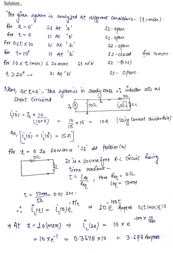
 Circuit 1 Transient response of a series RLC circuit The two switches in the circuit in Figure 8 operate synchronously. When switch 1 is in position "a", switch 2 is closed. When switch 1 is in position "b", switch 2 is open. Switch 1 has been in position "a" for a very long time. At 1-0, it moves instantaneously to position 4Ω t=0 2 8Ω 100mH 150V| 2Ω 60 V Figure 8: Circuit for Tasks 3 and 4 TASK 3...
QUESTION 1 The switch in the circuit seen in Figure has been in a position @...
 QUESTION 1 The switch in the circuit seen in Figure has been in a position @ for a long time. At t= 0 ,the switch moves instantaneously to position b AVM 10 kg 12.5 kg 120 (*) 150 kn ? 50 kn volt) = 40 nF ms Fill in the following values: Whent < 0: initial value Vc(0-) = When t = 0: Vo = When t > 0, time constant T = When t= 00, VF =D The final...
Problem 7.31 The switch in the circuit seen in the figure has been in position x...
 Problem 7.31 The switch in the circuit seen in the figure has been in position x for a long time. Att 0, the switch moves instantaneously to position y. (Figure 1) Part A Find ? so that the time constant for t > 0 is 40 ms a-Value Units Submit Request Answer Figure 1 of 1 Part B For the found ?, find t Express your answer in terms of t, where t is in seconds 20 k2 Ds 5...
2. The two switches in the following circuit operate synchronously. When switch-1 is open switch-2 is...
 2. The two switches in the following circuit operate synchronously. When switch-1 is open switch-2 is in position a. When switch-1 is closed, switch-2 moves to position b. Switch been open for a long time and then closes at t-0. Find iz(t) for 120.(40) -1 has 5 0 o 51 1H (t) 8 V 1 H 5 H 24? a.
Problem 7.10 2 of 2 The switch in the circuit seen in the figure has been...
 Problem 7.10 2 of 2 The switch in the circuit seen in the figure has been in position 1 for a long time. Att 0, the switch moves instantaneously to position 2. (Figure 1) PartA Find the value of R so that 28 % of the initial energy stored in the 10 mH inductor is dissipated in R in 16 s Express your answer with the appropriate units. R- 1 Value Units Submit Request Answer Figure 1 of 1 Return...
USE differential Approach in your analysis The switch in the circuit has been in position 1...
 USE differential Approach in your analysis The switch in the circuit has been in position 1 for a long time. At t = 0 it moves instantaneously to position 2. (Figure 1) 10 12 50 VO 331 31.5 HŽ 402 How many milliseconds after the switch operates does v, equal 160 V ?
4. The switch in the circuit in the figure below has been in position 'a' for...
 4. The switch in the circuit in the figure below has been in position 'a' for a long time. At t = 0, the switch moves instantaneously to position b. For t> 0*, find a) vo(t) b) io(t). 5k12 b 10 k 12 11 = 0 + 10 kn} 1,040nF 40 kN 75 V 100 V
2. The switch in the circuit shown in Figure 1 has been in position 'a' for...
 2. The switch in the circuit shown in Figure 1 has been in position 'a' for a long time. At t=0, the switch moves instantaneously to position b. a) Find the numerical expression for io(t) when t > 0. b) Find the numerical expression for volt) fort > 0 1 = 0 b! 51 602 45 A 2150 vo 20 10 mH 240 V 1
Problem 4:Consider a circuit with two switches, one ideal battery, one resistor, one capacitor and one...
 Problem 4:Consider a circuit with two switches, one ideal battery, one resistor, one capacitor and one inductor. The circuit is drawn below with both switches open: R-14.00 C ; 6.20 uF, and L 54.0 mH, and the ideal battery has emf ξ . 34.0 V. At t-o, both switches are open and the charge on the capacitor is qlt-0) (a) The switch is put at position "a". Compute the charge, oft-S us), on the capacitor after 5.00 microseconds (5x10 sec)...
Problem 8.15 only please 8.15 The resistor in the circuit of Fig. P8.14 is increased from...
 Problem 8.15 only please
8.15 The resistor in the circuit of Fig. P8.14 is increased from 100 to 125 N. Find v(t) for t 0. PSPICE 8.14 The two switches in the circuit seen in Fig. P8.14 operate synchronously. When switch 1 is in position a, switch 2 is in position d. When switch 1 move to position b, switch 2 moves to position c. Switch 1 has been in position a for a long time. At t = 0,...
Problem 8.15 only please
8.15 The resistor in the circuit of Fig. P8.14 is increased from 100 to 125 N. Find v(t) for t 0. PSPICE 8.14 The two switches in the circuit seen in Fig. P8.14 operate synchronously. When switch 1 is in position a, switch 2 is in position d. When switch 1 move to position b, switch 2 moves to position c. Switch 1 has been in position a for a long time. At t = 0,...
 Circuit 1 Transient response of a series RLC circuit The two switches in the circuit in Figure 8 operate synchronously. When switch 1 is in position "a", switch 2 is closed. When switch 1 is in position "b", switch 2 is open. Switch 1 has been in position "a" for a very long time. At 1-0, it moves instantaneously to position 4Ω t=0 2 8Ω 100mH 150V| 2Ω 60 V Figure 8: Circuit for Tasks 3 and 4 TASK 3...
 QUESTION 1 The switch in the circuit seen in Figure has been in a position @ for a long time. At t= 0 ,the switch moves instantaneously to position b AVM 10 kg 12.5 kg 120 (*) 150 kn ? 50 kn volt) = 40 nF ms Fill in the following values: Whent < 0: initial value Vc(0-) = When t = 0: Vo = When t > 0, time constant T = When t= 00, VF =D The final...
 Problem 7.31 The switch in the circuit seen in the figure has been in position x for a long time. Att 0, the switch moves instantaneously to position y. (Figure 1) Part A Find ? so that the time constant for t > 0 is 40 ms a-Value Units Submit Request Answer Figure 1 of 1 Part B For the found ?, find t Express your answer in terms of t, where t is in seconds 20 k2 Ds 5...
 2. The two switches in the following circuit operate synchronously. When switch-1 is open switch-2 is in position a. When switch-1 is closed, switch-2 moves to position b. Switch been open for a long time and then closes at t-0. Find iz(t) for 120.(40) -1 has 5 0 o 51 1H (t) 8 V 1 H 5 H 24? a.
 Problem 7.10 2 of 2 The switch in the circuit seen in the figure has been in position 1 for a long time. Att 0, the switch moves instantaneously to position 2. (Figure 1) PartA Find the value of R so that 28 % of the initial energy stored in the 10 mH inductor is dissipated in R in 16 s Express your answer with the appropriate units. R- 1 Value Units Submit Request Answer Figure 1 of 1 Return...
 USE differential Approach in your analysis The switch in the circuit has been in position 1 for a long time. At t = 0 it moves instantaneously to position 2. (Figure 1) 10 12 50 VO 331 31.5 HŽ 402 How many milliseconds after the switch operates does v, equal 160 V ?
 4. The switch in the circuit in the figure below has been in position 'a' for a long time. At t = 0, the switch moves instantaneously to position b. For t> 0*, find a) vo(t) b) io(t). 5k12 b 10 k 12 11 = 0 + 10 kn} 1,040nF 40 kN 75 V 100 V
 2. The switch in the circuit shown in Figure 1 has been in position 'a' for a long time. At t=0, the switch moves instantaneously to position b. a) Find the numerical expression for io(t) when t > 0. b) Find the numerical expression for volt) fort > 0 1 = 0 b! 51 602 45 A 2150 vo 20 10 mH 240 V 1
 Problem 4:Consider a circuit with two switches, one ideal battery, one resistor, one capacitor and one inductor. The circuit is drawn below with both switches open: R-14.00 C ; 6.20 uF, and L 54.0 mH, and the ideal battery has emf ξ . 34.0 V. At t-o, both switches are open and the charge on the capacitor is qlt-0) (a) The switch is put at position "a". Compute the charge, oft-S us), on the capacitor after 5.00 microseconds (5x10 sec)...
 Problem 8.15 only please
8.15 The resistor in the circuit of Fig. P8.14 is increased from 100 to 125 N. Find v(t) for t 0. PSPICE 8.14 The two switches in the circuit seen in Fig. P8.14 operate synchronously. When switch 1 is in position a, switch 2 is in position d. When switch 1 move to position b, switch 2 moves to position c. Switch 1 has been in position a for a long time. At t = 0,...
Problem 8.15 only please
8.15 The resistor in the circuit of Fig. P8.14 is increased from 100 to 125 N. Find v(t) for t 0. PSPICE 8.14 The two switches in the circuit seen in Fig. P8.14 operate synchronously. When switch 1 is in position a, switch 2 is in position d. When switch 1 move to position b, switch 2 moves to position c. Switch 1 has been in position a for a long time. At t = 0,...
Most questions answered within 3 hours.
-
Where is the error in this code sequence?
String s1 = "Hello";
String s2 = "ello";...
asked 11 months ago -
Financial data for Joel de Paris, Inc., for last year
follow:
Joel de Paris, Inc.
Balance...
asked 11 months ago -
Consider this reaction:
Al2(SO4)3 (aq)+ BaCl3
(aq) Al2Cl6 (aq)- +
3BaSO4(s) . What is the...
asked 11 months ago -
Suppose that Savneet is considering increasing her
recent random sample from 20 car rentals to 40...
asked 11 months ago -
Trucks arrive at an unloading terminal at an average rate of 120
per hour.
Trucks arrive...
asked 11 months ago -
Why are methanol and ethanol completely soluble in water while
octanol is not very little soluble....
asked 11 months ago -
A facilities manager at a university reads in a research report
that the mean amount of...
asked 11 months ago -
When the CuSO4 is rehydrated by adding water to the anhydrous
compound, is this an endothermic...
asked 11 months ago -
A ray of sunlight is passing from diamond into crown glass; the
angle of incidence is...
asked 11 months ago -
A block of mass 0.249 kg is placed on top of a light, vertical
spring of...
asked 11 months ago -
how do the kidneys compensate in the presences of acidosis
a) trigger hyperventilate
b) reserve acid...
asked 11 months ago -
Question 501 pts
The rental rate of capital to the firm increases. Which of the
following...
asked 11 months ago