
Homework Answers
Textbook = Mechanical enginnering design by Shigley's

 the goodman creterion is same
as soderberg creterion the only differenc is SY replace
SUT so in part4 we take direct values from part 3 if u
have problem in equations then cmt i will provide the equatins
the goodman creterion is same
as soderberg creterion the only differenc is SY replace
SUT so in part4 we take direct values from part 3 if u
have problem in equations then cmt i will provide the equatins
by the way you can easily get the book form net
best of luck
Add Answer to:
A shaft is loaded in bending and torsion such that Ma- 73.7 N-m, Ta -48.8 Nm,...
Ashalt is loaded in bending and torsion such that M = 70 N m , T....
 Ashalt is loaded in bending and torsion such that M = 70 N m , T. 45 N m, MA 55 N m , and T = 35 N m. For the shaft, S, = 700 MPa and S = 560 MPa, and a fully corrected endurance limit of S-210 MPa is assumed. Let Ky - 2.2 and K = 1.8. With a design factor of 2.0 determine the minimum acceptable diameter of the shalt using the (a) DE-Gerber criterion....
1) [40 pts] Determination of minimum shaft diameter using DE-Gerber, DE-ASME Elliptic, DE-Soderberg, and DE-Goodman criteria...
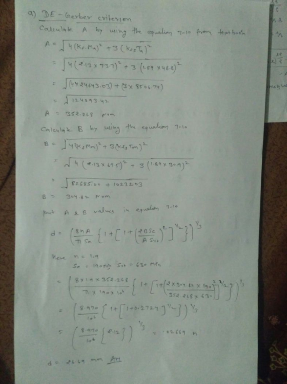
 1) [40 pts] Determination of minimum shaft diameter using DE-Gerber, DE-ASME Elliptic, DE-Soderberg, and DE-Goodman criteria A shaft is loaded in bending and torsion such that M. = 66 Nm, T. = 42.496 Nm, Mm = 51.858 Nm, and Tm = 33 N m. For the shaft, S, = 700 MPa and S, = 560 MPa, and a fully corrected endurance limit of S, = 210 MPa is assumed. Let K = 2.2 and Kis = 1.8. With a design...
2. (8 points) A solid shaft shown below is loaded in bending and torsion with steady...
 2. (8 points) A solid shaft shown below is loaded in bending and torsion with steady rotation. The total bending moment and torque diagrams are also given. The selected shaft steel material has an ultimate tensile strength Sut = 68kpsi, initial yield stress Sy = 57kpsi, and fully corrected factors for endurance limit, kakykekakek, = 0.60. (a) (6 points) Determine the factor of safety at point D of the shaft using DE-ASME Elliptic criterion. Assume K, = 1.8 and Kfs...
A 1020 steel shaft 3. A 1020 steel shaft has a corrected real endurance limit of...
 A 1020 steel shaft
3. A 1020 steel shaft has a corrected real endurance limit of Se 40 ksi and a tensile strength of Sut 64 ksi. The shaft is loaded in bending and torsion such that Ma 500 lbf.in, and Tm 300 lbf.in, Mm Ta 0. The stress concentration factors were determined to be Kr 2.25, and Kf 1.75. Provided the design engineer choose a diameter of d 1.0 in, determine the factor of safety n of the shaft...
A 1020 steel shaft
3. A 1020 steel shaft has a corrected real endurance limit of Se 40 ksi and a tensile strength of Sut 64 ksi. The shaft is loaded in bending and torsion such that Ma 500 lbf.in, and Tm 300 lbf.in, Mm Ta 0. The stress concentration factors were determined to be Kr 2.25, and Kf 1.75. Provided the design engineer choose a diameter of d 1.0 in, determine the factor of safety n of the shaft...
A rotating step shaft is loaded as shown, where the forces FA and FB are constant...
 A rotating step shaft is loaded as shown, where the forces FA and FB are constant at 610 lbf and 305 lbf, respectively, and the torque Talternates from 0 to 1800 lbf-in. The shaft is to be considered simply supported at points and Cand is made of AISI 1045 CD steel with a fully corrected endurance limit of Se= 40 kpsi. Let Kf= 2.1 and Kfs = 1.7. Take the value of design factor to be 2.5. 6 in 6...
-600 h 1. A rotating step shaft is loaded as shown, where the forces F. and...
 -600 h 1. A rotating step shaft is loaded as shown, where the forces F. and F: are constant at 600 lbf and 300 lbf, respectively, and the torque T alternates from 0 to 1800 Ibf in. The shaft is to be considered simply supported at points and C, and is made of AISI 1045 CD steel with a fully corrected endurance limit of Se = 40 kpsi. Let k, = 2.1 and K = 1.7. For a design factor...
A rotating step shaft is loaded as shown, where the forces FA and FB are constant...
 A rotating step shaft is loaded as shown, where the forces FA and FB are constant at 600 lbf and 300 lbf, respectively, and the torque T alternates from 0 to 1800 lbf . in. The shaft is to be considered simply supported at points and C, and is made of AISI 1045 CD steel with a fully corrected endurance limit of Se = 40 kpsi. Let Kg = 2.1 and K = 1.7. For a design factor of 2.5...
For a bolted assembly with eight bolts, the stiffness of cach bolt is k 1.0 MN/mm...
 For a bolted assembly with eight bolts, the stiffness of cach bolt is k 1.0 MN/mm and the stiffness of the members is k26 MN/mm per bolt. The bolts are preloaded to 75 peroner of proof strength. Assume the external load is equally distrihuted to all the bolts. The bolts am M6 x1 class 5.8 with rolled threads. A fluctuating external load is applied to the cntire with P 60 kN and P - 20 kN. (a) Determine the yielding...
 Ashalt is loaded in bending and torsion such that M = 70 N m , T. 45 N m, MA 55 N m , and T = 35 N m. For the shaft, S, = 700 MPa and S = 560 MPa, and a fully corrected endurance limit of S-210 MPa is assumed. Let Ky - 2.2 and K = 1.8. With a design factor of 2.0 determine the minimum acceptable diameter of the shalt using the (a) DE-Gerber criterion....
 1) [40 pts] Determination of minimum shaft diameter using DE-Gerber, DE-ASME Elliptic, DE-Soderberg, and DE-Goodman criteria A shaft is loaded in bending and torsion such that M. = 66 Nm, T. = 42.496 Nm, Mm = 51.858 Nm, and Tm = 33 N m. For the shaft, S, = 700 MPa and S, = 560 MPa, and a fully corrected endurance limit of S, = 210 MPa is assumed. Let K = 2.2 and Kis = 1.8. With a design...
 2. (8 points) A solid shaft shown below is loaded in bending and torsion with steady rotation. The total bending moment and torque diagrams are also given. The selected shaft steel material has an ultimate tensile strength Sut = 68kpsi, initial yield stress Sy = 57kpsi, and fully corrected factors for endurance limit, kakykekakek, = 0.60. (a) (6 points) Determine the factor of safety at point D of the shaft using DE-ASME Elliptic criterion. Assume K, = 1.8 and Kfs...
 A 1020 steel shaft
3. A 1020 steel shaft has a corrected real endurance limit of Se 40 ksi and a tensile strength of Sut 64 ksi. The shaft is loaded in bending and torsion such that Ma 500 lbf.in, and Tm 300 lbf.in, Mm Ta 0. The stress concentration factors were determined to be Kr 2.25, and Kf 1.75. Provided the design engineer choose a diameter of d 1.0 in, determine the factor of safety n of the shaft...
A 1020 steel shaft
3. A 1020 steel shaft has a corrected real endurance limit of Se 40 ksi and a tensile strength of Sut 64 ksi. The shaft is loaded in bending and torsion such that Ma 500 lbf.in, and Tm 300 lbf.in, Mm Ta 0. The stress concentration factors were determined to be Kr 2.25, and Kf 1.75. Provided the design engineer choose a diameter of d 1.0 in, determine the factor of safety n of the shaft...
 A rotating step shaft is loaded as shown, where the forces FA and FB are constant at 610 lbf and 305 lbf, respectively, and the torque Talternates from 0 to 1800 lbf-in. The shaft is to be considered simply supported at points and Cand is made of AISI 1045 CD steel with a fully corrected endurance limit of Se= 40 kpsi. Let Kf= 2.1 and Kfs = 1.7. Take the value of design factor to be 2.5. 6 in 6...
 -600 h 1. A rotating step shaft is loaded as shown, where the forces F. and F: are constant at 600 lbf and 300 lbf, respectively, and the torque T alternates from 0 to 1800 Ibf in. The shaft is to be considered simply supported at points and C, and is made of AISI 1045 CD steel with a fully corrected endurance limit of Se = 40 kpsi. Let k, = 2.1 and K = 1.7. For a design factor...
 A rotating step shaft is loaded as shown, where the forces FA and FB are constant at 600 lbf and 300 lbf, respectively, and the torque T alternates from 0 to 1800 lbf . in. The shaft is to be considered simply supported at points and C, and is made of AISI 1045 CD steel with a fully corrected endurance limit of Se = 40 kpsi. Let Kg = 2.1 and K = 1.7. For a design factor of 2.5...
 For a bolted assembly with eight bolts, the stiffness of cach bolt is k 1.0 MN/mm and the stiffness of the members is k26 MN/mm per bolt. The bolts are preloaded to 75 peroner of proof strength. Assume the external load is equally distrihuted to all the bolts. The bolts am M6 x1 class 5.8 with rolled threads. A fluctuating external load is applied to the cntire with P 60 kN and P - 20 kN. (a) Determine the yielding...
Most questions answered within 3 hours.
-
Where is the error in this code sequence?
String s1 = "Hello";
String s2 = "ello";...
asked 11 months ago -
Financial data for Joel de Paris, Inc., for last year
follow:
Joel de Paris, Inc.
Balance...
asked 11 months ago -
Consider this reaction:
Al2(SO4)3 (aq)+ BaCl3
(aq) Al2Cl6 (aq)- +
3BaSO4(s) . What is the...
asked 11 months ago -
Suppose that Savneet is considering increasing her
recent random sample from 20 car rentals to 40...
asked 11 months ago -
Trucks arrive at an unloading terminal at an average rate of 120
per hour.
Trucks arrive...
asked 11 months ago -
Why are methanol and ethanol completely soluble in water while
octanol is not very little soluble....
asked 11 months ago -
A facilities manager at a university reads in a research report
that the mean amount of...
asked 11 months ago -
When the CuSO4 is rehydrated by adding water to the anhydrous
compound, is this an endothermic...
asked 11 months ago -
A ray of sunlight is passing from diamond into crown glass; the
angle of incidence is...
asked 11 months ago -
A block of mass 0.249 kg is placed on top of a light, vertical
spring of...
asked 11 months ago -
how do the kidneys compensate in the presences of acidosis
a) trigger hyperventilate
b) reserve acid...
asked 11 months ago -
Question 501 pts
The rental rate of capital to the firm increases. Which of the
following...
asked 11 months ago