You are asked to design a circuit with a capacitance of 47µF and you have a...
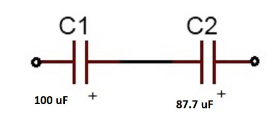
You are asked to design a circuit with a capacitance of 47µF and you have a whole box of assorted capacitors. Of course, there is everything but a 47µF capacitor in the box! The nicest capacitor in the box has a value of 100µF. What other value of a single capacitor could you combine with it to create the capacitance you need. Draw a circuit diagram showing how you would wire the combination. Would you wire it in series or parallel?
Homework Answers
Here ,
as the capacitance needed is less than the 100 uF
the capacitors must be connected in series
Ceq = 47 uF
C1 = 100 uF
let the capacitor needed is C2
for a series connection
1/Ceq = 1/C2 + 1/C1
1/47 = 1/100 + 1/C2
C2 = 88.7 uF
the capacitor neededis 88.7 uF
Add Answer to:
You are asked to design a circuit with a capacitance of 47µF and
you have a...
If you have two capacitors but you want to create a single circuit using a capacitor...
 If you have two capacitors but you want to create a single circuit using a capacitor that has less capacitance than either of the two that you have, how should you arrange the capacitors in your circuit? A. Put the capacitors in series. B. Put the capacitors in parallel. C. Put one before and one after the battery. D. Change the direction of one of the capacitors. E. It is not possible to have an equivalent capacitance less than any...
The C1 -2.0 uF and 3.0 uF capacitor equivalent capacitance is X1-5.0 μF. Likewise, the C2-3.0...
 The C1 -2.0 uF and 3.0 uF capacitor equivalent capacitance is X1-5.0 μF. Likewise, the C2-3.0 μF and 6.0 μF capacitors are also in parallel and have an equivalent capacitance of Y1-9.0屹The upper branch in Figure 26.11b now consists of a 4.0 μF capacitor and a 5.0 μF In series, which combine to give x2 according to the following equation. rs are in parallel and combine according to Ceq C1+C2. Their Likewise, the lower branch in Figure 26.11b consists of...
Find the total capacitance C tot of the combination of capacitors shown in the figure, where...
Find the total capacitance C tot of the combination of capacitors shown in the figure, where C 1 = 5.15 μF , C 2 = 3.55 μF , C 3 = 7.75 μF , C 4 = 1.25 μF , C 5 = 0.750 μF , and C 6 = 15.0 μF . A complex circuit containing 6 capacitors. The lead wire at the top of the diagram splits into three parallel branches that recombine at the bottom of the...
I need help trying to design this RC-circuit. PHYS 2120 LAB 6 - RC Circuit Capstone...
 I need help trying to design this RC-circuit.
PHYS 2120 LAB 6 - RC Circuit Capstone For example, if we wait long enough, eventually what do you expect the voltage over the capacitor to become? Part 1: Design an RC-circuit to charge a capacitor as quickly as possible. Your circuit must include the following elements (and only these elements): A Switch, a 10V Battery, a 0.1 F Capacitor, a 250 resistor, a 500 resistor, two 7512 resistors, a 1000 resistor,...
I need help trying to design this RC-circuit.
PHYS 2120 LAB 6 - RC Circuit Capstone For example, if we wait long enough, eventually what do you expect the voltage over the capacitor to become? Part 1: Design an RC-circuit to charge a capacitor as quickly as possible. Your circuit must include the following elements (and only these elements): A Switch, a 10V Battery, a 0.1 F Capacitor, a 250 resistor, a 500 resistor, two 7512 resistors, a 1000 resistor,...
A four-capacitor circuit is shown at right. Assume all four capacitors have different values of capacitance....
 A four-capacitor circuit is shown at right. Assume all four capacitors have different values of capacitance. 1. C2 and Cz are connected in series / parallel (circle one). Find their equivalent capacitance. v + c 2. Cz and C3 have the same / different (circle one) voltage drop across them. 3. C2 and C2 have the same / different (circle one) charge on their plates. A four-capacitor circuit is shown at right. Assume all four capacitors have different values of...
if you have two capacitors but you want to create a single drout using a capacitor...
 if you have two capacitors but you want to create a single drout using a capacitor that has less capacitance than either of the two that you have, how should you arrange the capacitors in your circuit? O A Put the capacitors in series 3. Put the capacitors in parte C. Put one before and one wter the battery D. Change the direction of one of the capacitors is not possible to have an equivalent capacitance less than any capacitor...
You have two capacitors, one is 6. 0 mu F the other is 3. 0 mu...
 You have two capacitors, one is 6. 0 mu F the other is 3. 0 mu F. You also have some wires and a 9. 0 V battery. Using the schematic symbols shown later in the lab, draw a diagram of a circuit with the two capacitors connected in series with the battery. Draw a diagram of a circuit using the same battery and capacitors with the capacitors now connected in parallel. Find the equivalent capacitance for each circuit. For...
4. In the capacitor circuit shown below, what is (A) the equivalent capacitance?i) Start by two...
 4. In the capacitor circuit shown below, what is (A) the equivalent capacitance?i) Start by two 2 μ F capacitors in series, ii) then combine result with the 5 μF capacitor in What is the charge on each capacitor? i) Start by determining the charge on the pacitor. ii) Then note that each parallel branch has 12 V because they are llel. (B) entire equivalent ca connected to the same battery, use that to determine the charge on each branch....
1. The capacitance through one branch of a circuit is measured to be 200 pF A...
 1. The capacitance through one branch of a circuit is measured to be 200 pF A capacitor is added to the circuit." effective capacitance is now measured to be 120 pF. a. Was the new capacitor added in series or in parallel to the circuit? Explain how you made your determinati b. What was the value of the added capacitor?
You need a capacitance of 55 μF , but you don't happen to have a 55...
You need a capacitance of 55 μF , but you don't happen to have a 55 μF capacitor. You do have a 85 μF capacitor. 1. What additional capacitor do you need to produce a total capacitance of 55 μF? Express your answer using two significant figures. 2. Should you join the two capacitors in parallel or in series?
 If you have two capacitors but you want to create a single circuit using a capacitor that has less capacitance than either of the two that you have, how should you arrange the capacitors in your circuit? A. Put the capacitors in series. B. Put the capacitors in parallel. C. Put one before and one after the battery. D. Change the direction of one of the capacitors. E. It is not possible to have an equivalent capacitance less than any...
 The C1 -2.0 uF and 3.0 uF capacitor equivalent capacitance is X1-5.0 μF. Likewise, the C2-3.0 μF and 6.0 μF capacitors are also in parallel and have an equivalent capacitance of Y1-9.0屹The upper branch in Figure 26.11b now consists of a 4.0 μF capacitor and a 5.0 μF In series, which combine to give x2 according to the following equation. rs are in parallel and combine according to Ceq C1+C2. Their Likewise, the lower branch in Figure 26.11b consists of...
 I need help trying to design this RC-circuit.
PHYS 2120 LAB 6 - RC Circuit Capstone For example, if we wait long enough, eventually what do you expect the voltage over the capacitor to become? Part 1: Design an RC-circuit to charge a capacitor as quickly as possible. Your circuit must include the following elements (and only these elements): A Switch, a 10V Battery, a 0.1 F Capacitor, a 250 resistor, a 500 resistor, two 7512 resistors, a 1000 resistor,...
I need help trying to design this RC-circuit.
PHYS 2120 LAB 6 - RC Circuit Capstone For example, if we wait long enough, eventually what do you expect the voltage over the capacitor to become? Part 1: Design an RC-circuit to charge a capacitor as quickly as possible. Your circuit must include the following elements (and only these elements): A Switch, a 10V Battery, a 0.1 F Capacitor, a 250 resistor, a 500 resistor, two 7512 resistors, a 1000 resistor,...
 A four-capacitor circuit is shown at right. Assume all four capacitors have different values of capacitance. 1. C2 and Cz are connected in series / parallel (circle one). Find their equivalent capacitance. v + c 2. Cz and C3 have the same / different (circle one) voltage drop across them. 3. C2 and C2 have the same / different (circle one) charge on their plates. A four-capacitor circuit is shown at right. Assume all four capacitors have different values of...
 if you have two capacitors but you want to create a single drout using a capacitor that has less capacitance than either of the two that you have, how should you arrange the capacitors in your circuit? O A Put the capacitors in series 3. Put the capacitors in parte C. Put one before and one wter the battery D. Change the direction of one of the capacitors is not possible to have an equivalent capacitance less than any capacitor...
 You have two capacitors, one is 6. 0 mu F the other is 3. 0 mu F. You also have some wires and a 9. 0 V battery. Using the schematic symbols shown later in the lab, draw a diagram of a circuit with the two capacitors connected in series with the battery. Draw a diagram of a circuit using the same battery and capacitors with the capacitors now connected in parallel. Find the equivalent capacitance for each circuit. For...
 4. In the capacitor circuit shown below, what is (A) the equivalent capacitance?i) Start by two 2 μ F capacitors in series, ii) then combine result with the 5 μF capacitor in What is the charge on each capacitor? i) Start by determining the charge on the pacitor. ii) Then note that each parallel branch has 12 V because they are llel. (B) entire equivalent ca connected to the same battery, use that to determine the charge on each branch....
 1. The capacitance through one branch of a circuit is measured to be 200 pF A capacitor is added to the circuit." effective capacitance is now measured to be 120 pF. a. Was the new capacitor added in series or in parallel to the circuit? Explain how you made your determinati b. What was the value of the added capacitor?
Most questions answered within 3 hours.
-
Where is the error in this code sequence?
String s1 = "Hello";
String s2 = "ello";...
asked 10 months ago -
Financial data for Joel de Paris, Inc., for last year
follow:
Joel de Paris, Inc.
Balance...
asked 10 months ago -
Consider this reaction:
Al2(SO4)3 (aq)+ BaCl3
(aq) Al2Cl6 (aq)- +
3BaSO4(s) . What is the...
asked 10 months ago -
Suppose that Savneet is considering increasing her
recent random sample from 20 car rentals to 40...
asked 10 months ago -
Trucks arrive at an unloading terminal at an average rate of 120
per hour.
Trucks arrive...
asked 10 months ago -
Why are methanol and ethanol completely soluble in water while
octanol is not very little soluble....
asked 10 months ago -
A facilities manager at a university reads in a research report
that the mean amount of...
asked 10 months ago -
When the CuSO4 is rehydrated by adding water to the anhydrous
compound, is this an endothermic...
asked 10 months ago -
A ray of sunlight is passing from diamond into crown glass; the
angle of incidence is...
asked 10 months ago -
A block of mass 0.249 kg is placed on top of a light, vertical
spring of...
asked 10 months ago -
how do the kidneys compensate in the presences of acidosis
a) trigger hyperventilate
b) reserve acid...
asked 10 months ago -
Question 501 pts
The rental rate of capital to the firm increases. Which of the
following...
asked 10 months ago