
Homework Answers

Add Answer to:
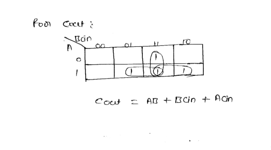
3) А B Cin- —S Cout Create the truth table fort he given digital circuit. Afterthat...
a full-adder circuit is used to add 2 bits A and B and the carry (Cin)...
a full-adder circuit is used to add 2 bits A and B and the carry (Cin) that resulted from the addition of the previous 2 bits. It then produces a SUM S and a carry out (Cout) that would be added to the more significant bits. Generate a truth table that has inputs A, B and Cin and the 2 outputs S and Cout. Find the logical function from the truth table and simplify it, if possible. Implement the function...
digital fundamentals thomas floyd Q8. A) Write the SOP (Minterm) Boolean expression for the truth table...
 digital fundamentals thomas floyd
Q8. A) Write the SOP (Minterm) Boolean expression for the truth table in Fig 2 below and draw the logic circuit that will perform the logic in the truth table in. B) Finally implement the same logic circuit by universal gates. [2+2=4] Inputs Output Inputs Output с в А Y C B A Y 0 0 0 0 0 0 0 0 0 1 0 0 1 0 0 0 1 1 1 0 1 1...
digital fundamentals thomas floyd
Q8. A) Write the SOP (Minterm) Boolean expression for the truth table in Fig 2 below and draw the logic circuit that will perform the logic in the truth table in. B) Finally implement the same logic circuit by universal gates. [2+2=4] Inputs Output Inputs Output с в А Y C B A Y 0 0 0 0 0 0 0 0 0 1 0 0 1 0 0 0 1 1 1 0 1 1...
1. There are two circuits in the following Truth Table (each is part of a Full...
1. There are two circuits in the following Truth Table (each is part of a Full Adder). Using Karnaugh Maps produce the circuit for Sum (S) given the inputs A, B, and Cin. A) Show the Karnaugh Map. B) Show the circuit. A B Cin SUM(S) Cout 0 0 0 0 0 0 0 1 1 0 0 1 0 1 0 0 1 1 0 1 1 0 0 1 0 1 0 1 0 1 1 1 0...
a) fill in truth table for A and read the number from top to bottom as...
 a) fill in truth table for A and read the number from
top to bottom as a binary number and convert to a decimal number
for your answer.
b) fill in truth table for B and read the number from
top to bottom as a binary number and convert to a decimal number
for your answer
c) fill in truth table for C and read the number from
top to bottom as a binary number and convert to a decimal...
a) fill in truth table for A and read the number from
top to bottom as a binary number and convert to a decimal number
for your answer.
b) fill in truth table for B and read the number from
top to bottom as a binary number and convert to a decimal number
for your answer
c) fill in truth table for C and read the number from
top to bottom as a binary number and convert to a decimal...
For Function F(a, b, c) = (a+b)' *c+a*b*c' +a*c Create the truth table Create the combinational...
For Function F(a, b, c) = (a+b)' *c+a*b*c' +a*c Create the truth table Create the combinational circuit implementing the function Reduce the circuit
(iii) The functionality of a digital unit is provided in the following table: S I Cin=0...
 (iii) The functionality of a digital unit is provided in the following table: S I Cin=0 Cin = 1 F = A + B (addition) F= A +1 (increment) F = A -1 (decrement) F=A+B'+1 (subtraction) Derive the MUX inputs lo, 11, 12, and 13 that implement that unit? Ici АНХ FA TIT MUX 4x1 Y; CH1 Show your work:
2. Given push buttons (A and B), coil relays (CR1 and CR2) and LED Light indicator, a) complete the truth table for the following relay logic circuit, and then b) complete a truth table for the...
 2. Given push buttons (A and B), coil relays (CR1 and CR2) and LED Light indicator, a) complete the truth table for the following relay logic circuit, and then b) complete a truth table for the same circuit, but when relay coil 2 failed open: (10pts) し2 CR1 CR2 CR1 CR2 Indicator True Table (Good Circuit) Output True Table (With Fault) B Output 0 0 0 0 1 0 0
2. Given push buttons (A and B), coil relays (CR1...
2. Given push buttons (A and B), coil relays (CR1 and CR2) and LED Light indicator, a) complete the truth table for the following relay logic circuit, and then b) complete a truth table for the same circuit, but when relay coil 2 failed open: (10pts) し2 CR1 CR2 CR1 CR2 Indicator True Table (Good Circuit) Output True Table (With Fault) B Output 0 0 0 0 1 0 0
2. Given push buttons (A and B), coil relays (CR1...
(2) (5 pomis) TL A-011000103, B = 011011012. Clearly 3. Conversion between truth table, circuit diagram...
 (2) (5 pomis) TL A-011000103, B = 011011012. Clearly 3. Conversion between truth table, circuit diagram and Boolean function. (1) (6 points) For the circuit below, write the Boolean expression F(A, B, C). Then write down the truth table for F. (2) (4 points) Draw a circuit schematic diagram which implements the following Boolean function. (Don't simplify the expression.) F(X2, X1, Xo) = x;'(x2+xo)' + xo'X1X2 (3) (10 points) The output of a logic function F(A,B,C) is one only if...
QUESTION 1 Suppose that an engineer wants to create a three bit adder using the method...
 QUESTION 1 Suppose that an engineer wants to create a three bit adder using the method described in Lecture 25. As part of the design process, the engineer creates the following building block component: a b Cin Full Adder Cout s In order to create the three bit adder, each of the three building blocks will need to be correctly connected together. In the circuit below, each of the possible connection points has been labeled with a number: A[2] 2...
A combination circuit is specified by the following Boolean functions listed below. h(a, b, c) = b,c' + a'c Implement the circuit with a 3x8 decoder. Provide truth table and drawing the l...
 A combination circuit is specified by the following Boolean functions listed below. h(a, b, c) = b,c' + a'c Implement the circuit with a 3x8 decoder. Provide truth table and drawing the logic/circuit diagram. Use the block diagram for the decoder provided in Figure A4 in supplements. Please label the inputs and outputs clearly. Note: use single 3x8 decoder Question 2 (15 points] A priority encoder is an encoder circuit that includes the Truth Table of a priority function. The...
 digital fundamentals thomas floyd
Q8. A) Write the SOP (Minterm) Boolean expression for the truth table in Fig 2 below and draw the logic circuit that will perform the logic in the truth table in. B) Finally implement the same logic circuit by universal gates. [2+2=4] Inputs Output Inputs Output с в А Y C B A Y 0 0 0 0 0 0 0 0 0 1 0 0 1 0 0 0 1 1 1 0 1 1...
digital fundamentals thomas floyd
Q8. A) Write the SOP (Minterm) Boolean expression for the truth table in Fig 2 below and draw the logic circuit that will perform the logic in the truth table in. B) Finally implement the same logic circuit by universal gates. [2+2=4] Inputs Output Inputs Output с в А Y C B A Y 0 0 0 0 0 0 0 0 0 1 0 0 1 0 0 0 1 1 1 0 1 1...
 a) fill in truth table for A and read the number from
top to bottom as a binary number and convert to a decimal number
for your answer.
b) fill in truth table for B and read the number from
top to bottom as a binary number and convert to a decimal number
for your answer
c) fill in truth table for C and read the number from
top to bottom as a binary number and convert to a decimal...
a) fill in truth table for A and read the number from
top to bottom as a binary number and convert to a decimal number
for your answer.
b) fill in truth table for B and read the number from
top to bottom as a binary number and convert to a decimal number
for your answer
c) fill in truth table for C and read the number from
top to bottom as a binary number and convert to a decimal...
 (iii) The functionality of a digital unit is provided in the following table: S I Cin=0 Cin = 1 F = A + B (addition) F= A +1 (increment) F = A -1 (decrement) F=A+B'+1 (subtraction) Derive the MUX inputs lo, 11, 12, and 13 that implement that unit? Ici АНХ FA TIT MUX 4x1 Y; CH1 Show your work:
 2. Given push buttons (A and B), coil relays (CR1 and CR2) and LED Light indicator, a) complete the truth table for the following relay logic circuit, and then b) complete a truth table for the same circuit, but when relay coil 2 failed open: (10pts) し2 CR1 CR2 CR1 CR2 Indicator True Table (Good Circuit) Output True Table (With Fault) B Output 0 0 0 0 1 0 0
2. Given push buttons (A and B), coil relays (CR1...
2. Given push buttons (A and B), coil relays (CR1 and CR2) and LED Light indicator, a) complete the truth table for the following relay logic circuit, and then b) complete a truth table for the same circuit, but when relay coil 2 failed open: (10pts) し2 CR1 CR2 CR1 CR2 Indicator True Table (Good Circuit) Output True Table (With Fault) B Output 0 0 0 0 1 0 0
2. Given push buttons (A and B), coil relays (CR1...
 (2) (5 pomis) TL A-011000103, B = 011011012. Clearly 3. Conversion between truth table, circuit diagram and Boolean function. (1) (6 points) For the circuit below, write the Boolean expression F(A, B, C). Then write down the truth table for F. (2) (4 points) Draw a circuit schematic diagram which implements the following Boolean function. (Don't simplify the expression.) F(X2, X1, Xo) = x;'(x2+xo)' + xo'X1X2 (3) (10 points) The output of a logic function F(A,B,C) is one only if...
 QUESTION 1 Suppose that an engineer wants to create a three bit adder using the method described in Lecture 25. As part of the design process, the engineer creates the following building block component: a b Cin Full Adder Cout s In order to create the three bit adder, each of the three building blocks will need to be correctly connected together. In the circuit below, each of the possible connection points has been labeled with a number: A[2] 2...
 A combination circuit is specified by the following Boolean functions listed below. h(a, b, c) = b,c' + a'c Implement the circuit with a 3x8 decoder. Provide truth table and drawing the logic/circuit diagram. Use the block diagram for the decoder provided in Figure A4 in supplements. Please label the inputs and outputs clearly. Note: use single 3x8 decoder Question 2 (15 points] A priority encoder is an encoder circuit that includes the Truth Table of a priority function. The...
Most questions answered within 3 hours.
-
Where is the error in this code sequence?
String s1 = "Hello";
String s2 = "ello";...
asked 10 months ago -
Financial data for Joel de Paris, Inc., for last year
follow:
Joel de Paris, Inc.
Balance...
asked 10 months ago -
Consider this reaction:
Al2(SO4)3 (aq)+ BaCl3
(aq) Al2Cl6 (aq)- +
3BaSO4(s) . What is the...
asked 10 months ago -
Suppose that Savneet is considering increasing her
recent random sample from 20 car rentals to 40...
asked 10 months ago -
Trucks arrive at an unloading terminal at an average rate of 120
per hour.
Trucks arrive...
asked 10 months ago -
Why are methanol and ethanol completely soluble in water while
octanol is not very little soluble....
asked 10 months ago -
A facilities manager at a university reads in a research report
that the mean amount of...
asked 10 months ago -
When the CuSO4 is rehydrated by adding water to the anhydrous
compound, is this an endothermic...
asked 10 months ago -
A ray of sunlight is passing from diamond into crown glass; the
angle of incidence is...
asked 10 months ago -
A block of mass 0.249 kg is placed on top of a light, vertical
spring of...
asked 10 months ago -
how do the kidneys compensate in the presences of acidosis
a) trigger hyperventilate
b) reserve acid...
asked 10 months ago -
Question 501 pts
The rental rate of capital to the firm increases. Which of the
following...
asked 10 months ago