

Homework Answers

Add Answer to:
A vibration sensor is used to measure the vibrations caused by a car engine. It is...
Filter A beam vibrates at 100 Hz. The vibrations are measured with a strain gage and...
 Filter A beam vibrates at 100 Hz. The vibrations are measured with a strain gage and Wheatstone bridge. The output voltage of the sensor is Vout = 2V s€, with Vs = 5.00 V the supply voltage and € = 8L/L the strain. The strain is in the range of +5 x 10⁻⁴. In addition, you know that: there is noise on the input: fnoise = 40,000Hz with amplitude 0.100 mV. The output is sent to your NI USB-6008 DAQ...
A resistive temperature sensor Rv (calibration curve shown below) is used to measure the temperature of...
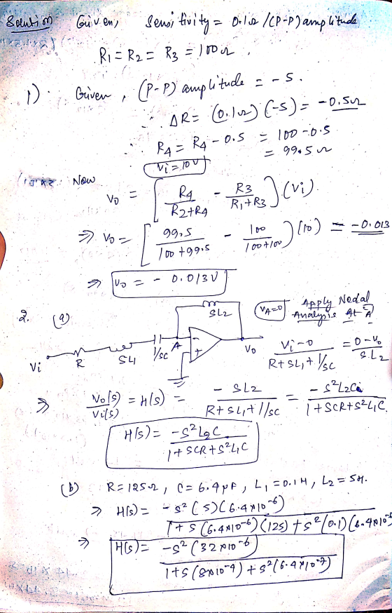
 A resistive temperature sensor Rv (calibration curve shown below) is used to measure the temperature of a process using Wheatstone bridge (Fig. 1). When the bridge is balanced, EO = OV. Then the Ry is inserted into a process whose temperature is 100C. Assume Ei = 10V, R1 = R2 = R3 = 4k12. 1. At which temperature the bridge is balanced? How much is EO at balanced mode? 2. Find the bridge output voltage E, a 3-significant figure voltmeter...
4. Analogue to digital converter (ADC) is one of the data processing. i. Describe the term quantization errot, sample af signal i ADK i. A 9 bits ADC is used in an electronic device for the mu...
 4. Analogue to digital converter (ADC) is one of the data processing. i. Describe the term quantization errot, sample af signal i ADK i. A 9 bits ADC is used in an electronic device for the murnt of analogue signal within the range of -TV to +TV. If an an measured as +3.2V, determine the value shows by the ADC (5 marks) The Wheatstone bridge circuit shown in the following figure is used to messure the resistance of a strain...
Hi could you please provide how to do problem 2? Amsterdam University of Applied Sciences Problem 2(15 points) A Wheatstone bridge is used to determine the resistance of a strain gauge. The 3 resista...
 Hi could you please provide how to do problem 2?
Amsterdam University of Applied Sciences Problem 2(15 points) A Wheatstone bridge is used to determine the resistance of a strain gauge. The 3 resistances R of the Wheatstone bridge are equal: R 200 12. When the strain gauge is fully relaxed (nd strain present), its resistance Rs is equal to the other 3 resistances: Rs-R. The strain is given bywith AR, the change in resistance in the strain gauge. The...
Hi could you please provide how to do problem 2?
Amsterdam University of Applied Sciences Problem 2(15 points) A Wheatstone bridge is used to determine the resistance of a strain gauge. The 3 resistances R of the Wheatstone bridge are equal: R 200 12. When the strain gauge is fully relaxed (nd strain present), its resistance Rs is equal to the other 3 resistances: Rs-R. The strain is given bywith AR, the change in resistance in the strain gauge. The...
The circuit shown in Figure Q4-1 includes an audio source and the equivalent circuit of a...
 The circuit shown in Figure Q4-1 includes an audio source and the equivalent circuit of a loudspeaker that you have been asked to analyse. 4. a) Assuming the speaker is to operate at a single frequency of 200 Hz and is5 driven by a cosinusoidal signal with peak amplitude of 20 V; determine the equivalent impedance of the speaker When connected to the audio source, calculate the current flow i() When testing the loudspeaker detailed in Q4a) i), you can...
A common source amplifier circuit based on a single n-channel MOSFET is shown in Figure 4b. Assume that the transconductance gm-60 mS (equivalent to mA/ V) and drain source resistance, os,...
 A common source amplifier circuit based on a single n-channel MOSFET is shown in Figure 4b. Assume that the transconductance gm-60 mS (equivalent to mA/ V) and drain source resistance, os, is so large it may be neglected. 0) Calculate the open circuit voltage gain Av Yout/ Vis. i) The amplifier has a load of 10 k2. Determine the current gain Va. = 12 V 150k 4k3 Vout Vin 200k GND = 0 V Figure 4b a) State the name...
Laboratory 1: operation amplifier characteristics A. Objectives: 1. To study the basic characteri...
 thanks
Laboratory 1: operation amplifier characteristics A. Objectives: 1. To study the basic characteristics of an operational amplifier 2. To study the bias circuit of an operational amplifier B. Apparatus: 1. DC Power supply 2. Experimental board and corresponding components 3. Electronic calculator (prepared by students) 4. Digital camera (prepared by students for photo taking of the experimental results) 5. Laptop computer with the software PicoScope 6 and Microsoft Word installed. 6. PicoScope PC Oscilloscope and its accessories. 7. Multimeter...
thanks
Laboratory 1: operation amplifier characteristics A. Objectives: 1. To study the basic characteristics of an operational amplifier 2. To study the bias circuit of an operational amplifier B. Apparatus: 1. DC Power supply 2. Experimental board and corresponding components 3. Electronic calculator (prepared by students) 4. Digital camera (prepared by students for photo taking of the experimental results) 5. Laptop computer with the software PicoScope 6 and Microsoft Word installed. 6. PicoScope PC Oscilloscope and its accessories. 7. Multimeter...
HI GUYS CAN YOU HELP ME SOLVE THIS QUESTION ASAP PLS AND THANKS!! QUESTION 6 ONLY,...
 HI GUYS CAN YOU HELP ME SOLVE THIS QUESTION ASAP PLS AND
THANKS!! QUESTION 6 ONLY, THE 15 MARK QUESTION. CAN YOU CALCULATE
THE THEOREATICAL VALUES WITH THESE 3 VALUES: 10HZ, 1KHZ, 10KHZ. AND
USING THIS VALUES. R = 1000Ω,C = 1µF, L = 0.23mh. not the L=44
thanks.
Exercise 2 [60 marks] RLC Circuit as a Low-pass Filter L 0000 in out Figure 2. RLC circuit 2 10 marks] Derive the second order input-output model (differential equation) for the...
HI GUYS CAN YOU HELP ME SOLVE THIS QUESTION ASAP PLS AND
THANKS!! QUESTION 6 ONLY, THE 15 MARK QUESTION. CAN YOU CALCULATE
THE THEOREATICAL VALUES WITH THESE 3 VALUES: 10HZ, 1KHZ, 10KHZ. AND
USING THIS VALUES. R = 1000Ω,C = 1µF, L = 0.23mh. not the L=44
thanks.
Exercise 2 [60 marks] RLC Circuit as a Low-pass Filter L 0000 in out Figure 2. RLC circuit 2 10 marks] Derive the second order input-output model (differential equation) for the...
Design a FULL WAVE BRIDGE RECTIFIER circuit that will: Take 120volts ac, 60 hz, sinusoidal waveform...
 Design a FULL WAVE BRIDGE RECTIFIER circuit that will:
Take 120volts ac, 60 hz, sinusoidal waveform and convert
it to a “regulated “dc value
giving 12 volts +, - 1 volt across a 2000-ohm output
load resistor with no more than 2%
ripple voltage.
You may assume:
a. An ideal power transformer as discussed in class.
b. For hand computations, you must assume a diode given by
Figure 4.8 page 185.
c. A filter capacitor sized per the textbook equation...
Design a FULL WAVE BRIDGE RECTIFIER circuit that will:
Take 120volts ac, 60 hz, sinusoidal waveform and convert
it to a “regulated “dc value
giving 12 volts +, - 1 volt across a 2000-ohm output
load resistor with no more than 2%
ripple voltage.
You may assume:
a. An ideal power transformer as discussed in class.
b. For hand computations, you must assume a diode given by
Figure 4.8 page 185.
c. A filter capacitor sized per the textbook equation...
Please explain which components should be used. A simple AM radio receiver can be constructed as a by the differential...
 Please explain which components should be used.
A simple AM radio receiver can be constructed as a by the differential equation series RLC circuit which can be modelled da R+ L Vext dt dt where L is the inductance, R is the restance, C is the capacitance, q is the resulting charge point in the circuit, and Vext is the voltage of the signal received in the circuit by an antenna When radio waves pass by the antennae, they create...
Please explain which components should be used.
A simple AM radio receiver can be constructed as a by the differential equation series RLC circuit which can be modelled da R+ L Vext dt dt where L is the inductance, R is the restance, C is the capacitance, q is the resulting charge point in the circuit, and Vext is the voltage of the signal received in the circuit by an antenna When radio waves pass by the antennae, they create...
 Filter A beam vibrates at 100 Hz. The vibrations are measured with a strain gage and Wheatstone bridge. The output voltage of the sensor is Vout = 2V s€, with Vs = 5.00 V the supply voltage and € = 8L/L the strain. The strain is in the range of +5 x 10⁻⁴. In addition, you know that: there is noise on the input: fnoise = 40,000Hz with amplitude 0.100 mV. The output is sent to your NI USB-6008 DAQ...
 A resistive temperature sensor Rv (calibration curve shown below) is used to measure the temperature of a process using Wheatstone bridge (Fig. 1). When the bridge is balanced, EO = OV. Then the Ry is inserted into a process whose temperature is 100C. Assume Ei = 10V, R1 = R2 = R3 = 4k12. 1. At which temperature the bridge is balanced? How much is EO at balanced mode? 2. Find the bridge output voltage E, a 3-significant figure voltmeter...
 4. Analogue to digital converter (ADC) is one of the data processing. i. Describe the term quantization errot, sample af signal i ADK i. A 9 bits ADC is used in an electronic device for the murnt of analogue signal within the range of -TV to +TV. If an an measured as +3.2V, determine the value shows by the ADC (5 marks) The Wheatstone bridge circuit shown in the following figure is used to messure the resistance of a strain...
 Hi could you please provide how to do problem 2?
Amsterdam University of Applied Sciences Problem 2(15 points) A Wheatstone bridge is used to determine the resistance of a strain gauge. The 3 resistances R of the Wheatstone bridge are equal: R 200 12. When the strain gauge is fully relaxed (nd strain present), its resistance Rs is equal to the other 3 resistances: Rs-R. The strain is given bywith AR, the change in resistance in the strain gauge. The...
Hi could you please provide how to do problem 2?
Amsterdam University of Applied Sciences Problem 2(15 points) A Wheatstone bridge is used to determine the resistance of a strain gauge. The 3 resistances R of the Wheatstone bridge are equal: R 200 12. When the strain gauge is fully relaxed (nd strain present), its resistance Rs is equal to the other 3 resistances: Rs-R. The strain is given bywith AR, the change in resistance in the strain gauge. The...
 The circuit shown in Figure Q4-1 includes an audio source and the equivalent circuit of a loudspeaker that you have been asked to analyse. 4. a) Assuming the speaker is to operate at a single frequency of 200 Hz and is5 driven by a cosinusoidal signal with peak amplitude of 20 V; determine the equivalent impedance of the speaker When connected to the audio source, calculate the current flow i() When testing the loudspeaker detailed in Q4a) i), you can...
 A common source amplifier circuit based on a single n-channel MOSFET is shown in Figure 4b. Assume that the transconductance gm-60 mS (equivalent to mA/ V) and drain source resistance, os, is so large it may be neglected. 0) Calculate the open circuit voltage gain Av Yout/ Vis. i) The amplifier has a load of 10 k2. Determine the current gain Va. = 12 V 150k 4k3 Vout Vin 200k GND = 0 V Figure 4b a) State the name...
 thanks
Laboratory 1: operation amplifier characteristics A. Objectives: 1. To study the basic characteristics of an operational amplifier 2. To study the bias circuit of an operational amplifier B. Apparatus: 1. DC Power supply 2. Experimental board and corresponding components 3. Electronic calculator (prepared by students) 4. Digital camera (prepared by students for photo taking of the experimental results) 5. Laptop computer with the software PicoScope 6 and Microsoft Word installed. 6. PicoScope PC Oscilloscope and its accessories. 7. Multimeter...
thanks
Laboratory 1: operation amplifier characteristics A. Objectives: 1. To study the basic characteristics of an operational amplifier 2. To study the bias circuit of an operational amplifier B. Apparatus: 1. DC Power supply 2. Experimental board and corresponding components 3. Electronic calculator (prepared by students) 4. Digital camera (prepared by students for photo taking of the experimental results) 5. Laptop computer with the software PicoScope 6 and Microsoft Word installed. 6. PicoScope PC Oscilloscope and its accessories. 7. Multimeter...
 HI GUYS CAN YOU HELP ME SOLVE THIS QUESTION ASAP PLS AND
THANKS!! QUESTION 6 ONLY, THE 15 MARK QUESTION. CAN YOU CALCULATE
THE THEOREATICAL VALUES WITH THESE 3 VALUES: 10HZ, 1KHZ, 10KHZ. AND
USING THIS VALUES. R = 1000Ω,C = 1µF, L = 0.23mh. not the L=44
thanks.
Exercise 2 [60 marks] RLC Circuit as a Low-pass Filter L 0000 in out Figure 2. RLC circuit 2 10 marks] Derive the second order input-output model (differential equation) for the...
HI GUYS CAN YOU HELP ME SOLVE THIS QUESTION ASAP PLS AND
THANKS!! QUESTION 6 ONLY, THE 15 MARK QUESTION. CAN YOU CALCULATE
THE THEOREATICAL VALUES WITH THESE 3 VALUES: 10HZ, 1KHZ, 10KHZ. AND
USING THIS VALUES. R = 1000Ω,C = 1µF, L = 0.23mh. not the L=44
thanks.
Exercise 2 [60 marks] RLC Circuit as a Low-pass Filter L 0000 in out Figure 2. RLC circuit 2 10 marks] Derive the second order input-output model (differential equation) for the...
 Design a FULL WAVE BRIDGE RECTIFIER circuit that will:
Take 120volts ac, 60 hz, sinusoidal waveform and convert
it to a “regulated “dc value
giving 12 volts +, - 1 volt across a 2000-ohm output
load resistor with no more than 2%
ripple voltage.
You may assume:
a. An ideal power transformer as discussed in class.
b. For hand computations, you must assume a diode given by
Figure 4.8 page 185.
c. A filter capacitor sized per the textbook equation...
Design a FULL WAVE BRIDGE RECTIFIER circuit that will:
Take 120volts ac, 60 hz, sinusoidal waveform and convert
it to a “regulated “dc value
giving 12 volts +, - 1 volt across a 2000-ohm output
load resistor with no more than 2%
ripple voltage.
You may assume:
a. An ideal power transformer as discussed in class.
b. For hand computations, you must assume a diode given by
Figure 4.8 page 185.
c. A filter capacitor sized per the textbook equation...
 Please explain which components should be used.
A simple AM radio receiver can be constructed as a by the differential equation series RLC circuit which can be modelled da R+ L Vext dt dt where L is the inductance, R is the restance, C is the capacitance, q is the resulting charge point in the circuit, and Vext is the voltage of the signal received in the circuit by an antenna When radio waves pass by the antennae, they create...
Please explain which components should be used.
A simple AM radio receiver can be constructed as a by the differential equation series RLC circuit which can be modelled da R+ L Vext dt dt where L is the inductance, R is the restance, C is the capacitance, q is the resulting charge point in the circuit, and Vext is the voltage of the signal received in the circuit by an antenna When radio waves pass by the antennae, they create...
Most questions answered within 3 hours.
-
Where is the error in this code sequence?
String s1 = "Hello";
String s2 = "ello";...
asked 10 months ago -
Financial data for Joel de Paris, Inc., for last year
follow:
Joel de Paris, Inc.
Balance...
asked 10 months ago -
Consider this reaction:
Al2(SO4)3 (aq)+ BaCl3
(aq) Al2Cl6 (aq)- +
3BaSO4(s) . What is the...
asked 10 months ago -
Suppose that Savneet is considering increasing her
recent random sample from 20 car rentals to 40...
asked 10 months ago -
Trucks arrive at an unloading terminal at an average rate of 120
per hour.
Trucks arrive...
asked 10 months ago -
Why are methanol and ethanol completely soluble in water while
octanol is not very little soluble....
asked 10 months ago -
A facilities manager at a university reads in a research report
that the mean amount of...
asked 10 months ago -
When the CuSO4 is rehydrated by adding water to the anhydrous
compound, is this an endothermic...
asked 10 months ago -
A ray of sunlight is passing from diamond into crown glass; the
angle of incidence is...
asked 10 months ago -
A block of mass 0.249 kg is placed on top of a light, vertical
spring of...
asked 10 months ago -
how do the kidneys compensate in the presences of acidosis
a) trigger hyperventilate
b) reserve acid...
asked 10 months ago -
Question 501 pts
The rental rate of capital to the firm increases. Which of the
following...
asked 10 months ago