Fill in the missing parameters in the table below. * Use standard values for the resistors....
Fill in the missing parameters in the table below. * Use standard values for the resistors.
|
VCC |
R1 |
R2 |
VB |
|
12 V |
3 kΩ |
1 kΩ |
3 V |
|
12 V |
2 kΩ |
6 V |
|
|
12 V |
1 kΩ |
4 V |
|
|
10 V |
6.65 kΩ |
330 mV |
|
|
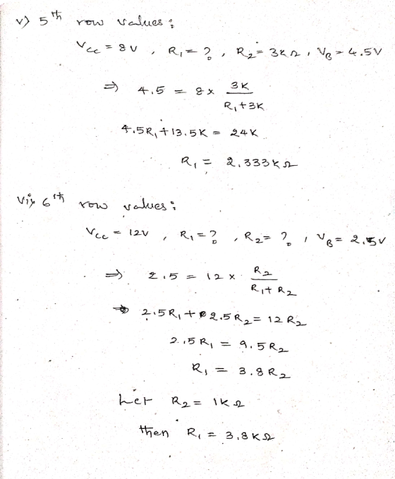
8 V |
3 kΩ |
4.5 V |
|
|
12 V |
2.5 V |
Table 1 – BJT Circuit
Homework Answers


If you have any doubts please ask in the comments section...
Please give like if you like the answer...
Thank you... Have a good day...
Add Answer to:
Fill in the missing parameters in the table below. * Use
standard values for the resistors....
The circuit shown in the figure below contains three resistors (R1, R2, and R3) and three...
 The circuit shown in the figure below contains three resistors (R1, R2, and R3) and three batteries (VA, VB, and Vc). The resistor values are: R1=2 Ohms, R2=R3=4 Ohms, and the battery voltages are Va=25 V, V8=15 V, and Vc=20 V. When the circuit is connected what will be the current through R2? Vc R1 + VB R2 R3 0.75 A 1.25 A 2.5 A 3.0 A 3.75 A
Question 8 5 pts The circuit shown in the figure below contains three resistors (R1, R2,...
 Question 8 5 pts The circuit shown in the figure below contains three resistors (R1, R2, and R3) and three batteries (VA, VB, and Vc). The resistor values are: R1=2 Ohms, R2=R3=4 Ohms, and the battery voltages are Va=25 V, V8=15 V, and Vc=20 V. When the circuit is connected what will be the current through Rz? VC R13 VA VB R2 R3 O 0.75 A O 1.25 A O 2.5 A O 3.0 A O 3.75 A
I don't need the measured values 1) Given the circuit in Figure 2 below, fill in...
 I don't need the measured values
1) Given the circuit in Figure 2 below, fill in Table 2 and 3 with the missing information. See the following Procedure B. N2 ETH V R2 VR4 Ref Node Figure 2 PS The blue power supply R1 120 ohms R2 220 ohms R3 330 ohms R330 ohms RL1000 ohm variable potentiometer Page 3
I don't need the measured values
1) Given the circuit in Figure 2 below, fill in Table 2 and 3 with the missing information. See the following Procedure B. N2 ETH V R2 VR4 Ref Node Figure 2 PS The blue power supply R1 120 ohms R2 220 ohms R3 330 ohms R330 ohms RL1000 ohm variable potentiometer Page 3
The circuit shown in the figure below contains three resistors (R1, R2, and R3) and three...
 The circuit shown in the figure below contains three resistors
(R1, R2, and R3) and three batteries (VA, VB, and VC). The resistor
values are: R1=2 Ohms, R2=R3=8 Ohms, and the battery voltages are
VA=25 V, VB=15 V, and VC=20 V. When the circuit is connected, what
will be the power dissipated by R3?
0.75 W
1.25 W
2.67 W
4.2 W
5.5 W
Vc + R1 + VA VB R2 R3
The circuit shown in the figure below contains three resistors
(R1, R2, and R3) and three batteries (VA, VB, and VC). The resistor
values are: R1=2 Ohms, R2=R3=8 Ohms, and the battery voltages are
VA=25 V, VB=15 V, and VC=20 V. When the circuit is connected, what
will be the power dissipated by R3?
0.75 W
1.25 W
2.67 W
4.2 W
5.5 W
Vc + R1 + VA VB R2 R3
The circuit shown in the figure below contains three resistors (R1, R2, and R3) and three...
 The circuit shown in the figure below contains three resistors (R1, R2, and R3) and three batteries (VA, VB, and Vc). The resistor values are: R1=2 Ohms, R2=R3=8 Ohms, and the battery voltages are VA=25 V, V8=15 V, and Vc=20 V. When the circuit is connected, what will be the power dissipated by R3? Vc + R1 3 + VB R2 R3 O 0.75 W O 1.25 W 0 2.67 W 4.2 W O 5.5 W
The circuit shown in the figure below contains three resistors (R1, R2, three batteries (VA, V8,...
 The circuit shown in the figure below contains three resistors (R1, R2, three batteries (VA, V8, and Vc). The resistor values are: R1-2 Ohms, R2=R3=4 Ohms, and the battery voltages are Va=25 V, VB=15 V, and Vc=20 V. When the circuit is connected what will be the current through R2? VC R1 ** VA ++ VE R2 ho {} R3 0.75 A 1.25 A O 2.5 A O 3.0 A 375 A
1. Determine values for resistors R1 and RC to obtain l = 4.58 mA and Vce...
 1. Determine values for resistors R1 and RC to obtain l = 4.58 mA and Vce = 4.5 V. Assume ß = 200 and Vse = 0.7 V for your analysis. 10v R1 ??? RC ???? M Q2 L2N3904 ZR2 10k Figure 2 Standard BJT DC Biasing Circuit
The circuit shown in the figure below contains three resistors (R1, R2, and R3) and three...
 The circuit shown in the figure below contains three resistors
(R1, R2, and R3) and three
batteries (VA, VB, and VC). The
resistor values are: R1=2 Ohms,
R2=R3=8 Ohms, and the battery voltages are
VA=25 V, VB=15 V, and VC=20 V.
When the circuit is connected, what will be the power dissipated by
R3?
0.75 W
1.25 W
2.67 W
4.2 W
5.5 W
VC HA R1 + + VA VB R2 m R3
The circuit shown in the figure below contains three resistors
(R1, R2, and R3) and three
batteries (VA, VB, and VC). The
resistor values are: R1=2 Ohms,
R2=R3=8 Ohms, and the battery voltages are
VA=25 V, VB=15 V, and VC=20 V.
When the circuit is connected, what will be the power dissipated by
R3?
0.75 W
1.25 W
2.67 W
4.2 W
5.5 W
VC HA R1 + + VA VB R2 m R3
Question 8 5 pts The circuit shown in the figure below contains three resistors (R1, R2,...
 Question 8 5 pts The circuit shown in the figure below contains three resistors (R1, R2, and R3) and three batteries (VA, VB, and Vc). The resistor values are: R1=2 Ohms, R2=R3=4 Ohms, and the battery voltages are VA=25 V, VB=15 V, and Vc=20 V. When the circuit is connected, what will be the power dissipated by R1? VC + R1 + VA VB R2 M R3 1.25 W 2.0 W 12.5 W 6.25 W 8.13 W
The circuit shown in the figure below contains three resistors (R1, R2, and R3) and three...
 The circuit shown in the figure below contains three resistors (R1, R2, and R3) and three batteries (VĄ, VB, and Vc). The resistor values are: R1=2 Ohms, R2=R3=6 Ohms, and the battery voltages are VA=25 V, VB=15 V, and Vc=20 V. When the circuit is connected, what will be the power dissipated by R2? VC HA R1 + VA + VB R2 my R3
 The circuit shown in the figure below contains three resistors (R1, R2, and R3) and three batteries (VA, VB, and Vc). The resistor values are: R1=2 Ohms, R2=R3=4 Ohms, and the battery voltages are Va=25 V, V8=15 V, and Vc=20 V. When the circuit is connected what will be the current through R2? Vc R1 + VB R2 R3 0.75 A 1.25 A 2.5 A 3.0 A 3.75 A
 Question 8 5 pts The circuit shown in the figure below contains three resistors (R1, R2, and R3) and three batteries (VA, VB, and Vc). The resistor values are: R1=2 Ohms, R2=R3=4 Ohms, and the battery voltages are Va=25 V, V8=15 V, and Vc=20 V. When the circuit is connected what will be the current through Rz? VC R13 VA VB R2 R3 O 0.75 A O 1.25 A O 2.5 A O 3.0 A O 3.75 A
 I don't need the measured values
1) Given the circuit in Figure 2 below, fill in Table 2 and 3 with the missing information. See the following Procedure B. N2 ETH V R2 VR4 Ref Node Figure 2 PS The blue power supply R1 120 ohms R2 220 ohms R3 330 ohms R330 ohms RL1000 ohm variable potentiometer Page 3
I don't need the measured values
1) Given the circuit in Figure 2 below, fill in Table 2 and 3 with the missing information. See the following Procedure B. N2 ETH V R2 VR4 Ref Node Figure 2 PS The blue power supply R1 120 ohms R2 220 ohms R3 330 ohms R330 ohms RL1000 ohm variable potentiometer Page 3
 The circuit shown in the figure below contains three resistors
(R1, R2, and R3) and three batteries (VA, VB, and VC). The resistor
values are: R1=2 Ohms, R2=R3=8 Ohms, and the battery voltages are
VA=25 V, VB=15 V, and VC=20 V. When the circuit is connected, what
will be the power dissipated by R3?
0.75 W
1.25 W
2.67 W
4.2 W
5.5 W
Vc + R1 + VA VB R2 R3
The circuit shown in the figure below contains three resistors
(R1, R2, and R3) and three batteries (VA, VB, and VC). The resistor
values are: R1=2 Ohms, R2=R3=8 Ohms, and the battery voltages are
VA=25 V, VB=15 V, and VC=20 V. When the circuit is connected, what
will be the power dissipated by R3?
0.75 W
1.25 W
2.67 W
4.2 W
5.5 W
Vc + R1 + VA VB R2 R3
 The circuit shown in the figure below contains three resistors (R1, R2, and R3) and three batteries (VA, VB, and Vc). The resistor values are: R1=2 Ohms, R2=R3=8 Ohms, and the battery voltages are VA=25 V, V8=15 V, and Vc=20 V. When the circuit is connected, what will be the power dissipated by R3? Vc + R1 3 + VB R2 R3 O 0.75 W O 1.25 W 0 2.67 W 4.2 W O 5.5 W
 The circuit shown in the figure below contains three resistors (R1, R2, three batteries (VA, V8, and Vc). The resistor values are: R1-2 Ohms, R2=R3=4 Ohms, and the battery voltages are Va=25 V, VB=15 V, and Vc=20 V. When the circuit is connected what will be the current through R2? VC R1 ** VA ++ VE R2 ho {} R3 0.75 A 1.25 A O 2.5 A O 3.0 A 375 A
 1. Determine values for resistors R1 and RC to obtain l = 4.58 mA and Vce = 4.5 V. Assume ß = 200 and Vse = 0.7 V for your analysis. 10v R1 ??? RC ???? M Q2 L2N3904 ZR2 10k Figure 2 Standard BJT DC Biasing Circuit
 The circuit shown in the figure below contains three resistors
(R1, R2, and R3) and three
batteries (VA, VB, and VC). The
resistor values are: R1=2 Ohms,
R2=R3=8 Ohms, and the battery voltages are
VA=25 V, VB=15 V, and VC=20 V.
When the circuit is connected, what will be the power dissipated by
R3?
0.75 W
1.25 W
2.67 W
4.2 W
5.5 W
VC HA R1 + + VA VB R2 m R3
The circuit shown in the figure below contains three resistors
(R1, R2, and R3) and three
batteries (VA, VB, and VC). The
resistor values are: R1=2 Ohms,
R2=R3=8 Ohms, and the battery voltages are
VA=25 V, VB=15 V, and VC=20 V.
When the circuit is connected, what will be the power dissipated by
R3?
0.75 W
1.25 W
2.67 W
4.2 W
5.5 W
VC HA R1 + + VA VB R2 m R3
 Question 8 5 pts The circuit shown in the figure below contains three resistors (R1, R2, and R3) and three batteries (VA, VB, and Vc). The resistor values are: R1=2 Ohms, R2=R3=4 Ohms, and the battery voltages are VA=25 V, VB=15 V, and Vc=20 V. When the circuit is connected, what will be the power dissipated by R1? VC + R1 + VA VB R2 M R3 1.25 W 2.0 W 12.5 W 6.25 W 8.13 W
 The circuit shown in the figure below contains three resistors (R1, R2, and R3) and three batteries (VĄ, VB, and Vc). The resistor values are: R1=2 Ohms, R2=R3=6 Ohms, and the battery voltages are VA=25 V, VB=15 V, and Vc=20 V. When the circuit is connected, what will be the power dissipated by R2? VC HA R1 + VA + VB R2 my R3
Most questions answered within 3 hours.
-
Where is the error in this code sequence?
String s1 = "Hello";
String s2 = "ello";...
asked 11 months ago -
Financial data for Joel de Paris, Inc., for last year
follow:
Joel de Paris, Inc.
Balance...
asked 11 months ago -
Consider this reaction:
Al2(SO4)3 (aq)+ BaCl3
(aq) Al2Cl6 (aq)- +
3BaSO4(s) . What is the...
asked 11 months ago -
Suppose that Savneet is considering increasing her
recent random sample from 20 car rentals to 40...
asked 11 months ago -
Trucks arrive at an unloading terminal at an average rate of 120
per hour.
Trucks arrive...
asked 11 months ago -
Why are methanol and ethanol completely soluble in water while
octanol is not very little soluble....
asked 11 months ago -
A facilities manager at a university reads in a research report
that the mean amount of...
asked 11 months ago -
When the CuSO4 is rehydrated by adding water to the anhydrous
compound, is this an endothermic...
asked 11 months ago -
A ray of sunlight is passing from diamond into crown glass; the
angle of incidence is...
asked 11 months ago -
A block of mass 0.249 kg is placed on top of a light, vertical
spring of...
asked 11 months ago -
how do the kidneys compensate in the presences of acidosis
a) trigger hyperventilate
b) reserve acid...
asked 11 months ago -
Question 501 pts
The rental rate of capital to the firm increases. Which of the
following...
asked 11 months ago