find a logic circuit that gives an output logic signal, X, which is high when an...
Homework Answers
|
INPUTs |
OUTPUT |
|||
|
B8 |
B4 |
B2 |
B1 |
X |
|
0 |
0 |
0 |
0 |
0 |
|
0 |
0 |
0 |
1 |
0 |
|
0 |
0 |
1 |
0 |
0 |
|
0 |
0 |
1 |
1 |
0 |
|
0 |
1 |
0 |
0 |
0 |
|
0 |
1 |
0 |
1 |
0 |
|
0 |
1 |
1 |
0 |
0 |
|
0 |
1 |
1 |
1 |
0 |
|
1 |
0 |
0 |
0 |
0 |
|
1 |
0 |
0 |
1 |
0 |
|
1 |
0 |
1 |
0 |
1 |
|
1 |
0 |
1 |
1 |
1 |
|
1 |
1 |
0 |
0 |
1 |
|
1 |
1 |
0 |
1 |
1 |
|
1 |
1 |
1 |
0 |
1 |
|
1 |
1 |
1 |
1 |
1 |

Add Answer to:
find a logic circuit that gives an output logic signal, X, which is
high when an...
13.4 LIRIY WILL Write a DUI expeSSIUI IUI ed UL ce su u 13.4 We need...
 13.4
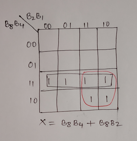
LIRIY WILL Write a DUI expeSSIUI IUI ed UL ce su u 13.4 We need a logic circuit that gives an output logic signal X which is high when an error in the form of an unused code occurs in a given BCD codeword. The inputs to the logic circuit are the bits B3, B4, B, and B, of the BCD codeword. Start by constructing a truth table for X. Then K-map it and go from there, whistling while...
13.4
LIRIY WILL Write a DUI expeSSIUI IUI ed UL ce su u 13.4 We need a logic circuit that gives an output logic signal X which is high when an error in the form of an unused code occurs in a given BCD codeword. The inputs to the logic circuit are the bits B3, B4, B, and B, of the BCD codeword. Start by constructing a truth table for X. Then K-map it and go from there, whistling while...
Design a logic circuit that will allow the passage of an input signal only when control...
Design a logic circuit that will allow the passage of an input signal only when control inputs B or C is LOW (use either B or C but not both are low) at the same time that D is HIGH. Otherwise, the output is LOW. Show the truth table and reduced expression for the output.
[5 pts] Design a circuit with three inputs (x,y,z) and one output that outputs true if the binary value of the inputs i...
 [5 pts] Design a circuit with three inputs (x,y,z) and one output that outputs true if the binary value of the inputs is a perfect square (it's square root is an integer). Construct the truth table, simplify using a K-map, and draw out the logic circuit diagram
[5 pts] Design a circuit with three inputs (x,y,z) and one output that outputs true if the binary value of the inputs is a perfect square (it's square root is an integer). Construct...
[5 pts] Design a circuit with three inputs (x,y,z) and one output that outputs true if the binary value of the inputs is a perfect square (it's square root is an integer). Construct the truth table, simplify using a K-map, and draw out the logic circuit diagram
[5 pts] Design a circuit with three inputs (x,y,z) and one output that outputs true if the binary value of the inputs is a perfect square (it's square root is an integer). Construct...
0 0 0 0 (a) Write the Boolean equation for the output X of the truth...
 0 0 0 0 (a) Write the Boolean equation for the output X of the truth table above (b) By using K-map, determine the expression of X in the form of product-of-sum and sum of-product. (c) Draw the logic circuits representing the expression of X in the form of product-of-sum and sum-of-product. Determine which configuration gives the lowest cost solution.
digital logic & design questions 1. Find the output function of this circuit, X. B C...
 digital logic & design questions
1. Find the output function of this circuit, X. B C 2. Use k-map to simplify the function X to its minimum Sum Of Product (SOP Draw the logic circuit of the simplified function X using the 74LS54 And Or Invert (AOD chip. 3. 74LSS4 Problem#4: The logic circuit in (a) is implemented using a 7400 IC chip. The conections on is not working properly! the problem is in the IC connections or in the...
digital logic & design questions
1. Find the output function of this circuit, X. B C 2. Use k-map to simplify the function X to its minimum Sum Of Product (SOP Draw the logic circuit of the simplified function X using the 74LS54 And Or Invert (AOD chip. 3. 74LSS4 Problem#4: The logic circuit in (a) is implemented using a 7400 IC chip. The conections on is not working properly! the problem is in the IC connections or in the...
Student ID K-map to simply the function f e and "d" is the least si (3 points each) CO: 3] 3. Five bits of information and a parity bit are to be transmitted on a noisy channel. The trans...
 Student ID K-map to simply the function f e and "d" is the least si (3 points each) CO: 3] 3. Five bits of information and a parity bit are to be transmitted on a noisy channel. The transmittor a. the parity checker circuits using Only 3-imput logic gates where the unused inpunts)-if any- must be connected to either O or 1, as appropriate. (show the cireuit). (3 points for each circuit for a total of 6 points) ver have...
DESIGN SECTION Before the experiment, you are going to design a circuit which has 4 inputs...
DESIGN SECTION Before the experiment, you are going to design a circuit which has 4 inputs w, x, y, z and an output F. If 4-bits input value is “odd number which is higher than 4”, or “3-bits highest even number” or “4-bits highest even number”, the output function F will be equal to 1. Otherwise F=0. Each students have to design the circuit and have to do following steps own by own. You are going to; a) Fill the...
Write the Boolean expression that implements the function, F(W,X,Y,Z) = ∑m(1,7,8,10,13) as a 4. NAND-NAND circuit...
Write the Boolean expression that implements the function, F(W,X,Y,Z) = ∑m(1,7,8,10,13) as a 4. NAND-NAND circuit 5. OR-NAND circuit 6. NOR-OR 7. Construct the truth table, K-map minimization, boolean expressions and circuit diagrams for all output bits of a circuit that performs 1’s complement of a 4-bit binary number. Assume overflow bits are lost:
Design a combinational logic circuit which has one output Z and a 4-bit input ABCD representing...
Design a combinational logic circuit which has one output Z and a 4-bit input ABCD representing a binary number. Z should be 1 iff the input is at least 5, but is no greater than 11. Use one OR gate (three inputs) and three AND gates (with no more than three inputs each). Using K-map, find min SOP and min POS form for the outputs W, X
Q6. a) Write the output expression for the circuit shown in the figure. b) Develop truth...
 Q6. a) Write the output expression for the circuit shown in the figure. b) Develop truth table for the circuit. (1 Mark) (4 Marks) A B C 13 X D Fig.2 07 [5] a) Minimize the following logic function using K-Map. b) Implement the minimized expression using basic gates. (3 Marks) (2 Marks) F(A,B,C,D) = (0,2,5,7,8,10,13,15) Q8 a) Write the output expression of the logic circuit shown in the figure. b) Minimize the expression using Boolean laws and theorems. C)...
 13.4
LIRIY WILL Write a DUI expeSSIUI IUI ed UL ce su u 13.4 We need a logic circuit that gives an output logic signal X which is high when an error in the form of an unused code occurs in a given BCD codeword. The inputs to the logic circuit are the bits B3, B4, B, and B, of the BCD codeword. Start by constructing a truth table for X. Then K-map it and go from there, whistling while...
13.4
LIRIY WILL Write a DUI expeSSIUI IUI ed UL ce su u 13.4 We need a logic circuit that gives an output logic signal X which is high when an error in the form of an unused code occurs in a given BCD codeword. The inputs to the logic circuit are the bits B3, B4, B, and B, of the BCD codeword. Start by constructing a truth table for X. Then K-map it and go from there, whistling while...
 [5 pts] Design a circuit with three inputs (x,y,z) and one output that outputs true if the binary value of the inputs is a perfect square (it's square root is an integer). Construct the truth table, simplify using a K-map, and draw out the logic circuit diagram
[5 pts] Design a circuit with three inputs (x,y,z) and one output that outputs true if the binary value of the inputs is a perfect square (it's square root is an integer). Construct...
[5 pts] Design a circuit with three inputs (x,y,z) and one output that outputs true if the binary value of the inputs is a perfect square (it's square root is an integer). Construct the truth table, simplify using a K-map, and draw out the logic circuit diagram
[5 pts] Design a circuit with three inputs (x,y,z) and one output that outputs true if the binary value of the inputs is a perfect square (it's square root is an integer). Construct...
 0 0 0 0 (a) Write the Boolean equation for the output X of the truth table above (b) By using K-map, determine the expression of X in the form of product-of-sum and sum of-product. (c) Draw the logic circuits representing the expression of X in the form of product-of-sum and sum-of-product. Determine which configuration gives the lowest cost solution.
 digital logic & design questions
1. Find the output function of this circuit, X. B C 2. Use k-map to simplify the function X to its minimum Sum Of Product (SOP Draw the logic circuit of the simplified function X using the 74LS54 And Or Invert (AOD chip. 3. 74LSS4 Problem#4: The logic circuit in (a) is implemented using a 7400 IC chip. The conections on is not working properly! the problem is in the IC connections or in the...
digital logic & design questions
1. Find the output function of this circuit, X. B C 2. Use k-map to simplify the function X to its minimum Sum Of Product (SOP Draw the logic circuit of the simplified function X using the 74LS54 And Or Invert (AOD chip. 3. 74LSS4 Problem#4: The logic circuit in (a) is implemented using a 7400 IC chip. The conections on is not working properly! the problem is in the IC connections or in the...
 Student ID K-map to simply the function f e and "d" is the least si (3 points each) CO: 3] 3. Five bits of information and a parity bit are to be transmitted on a noisy channel. The transmittor a. the parity checker circuits using Only 3-imput logic gates where the unused inpunts)-if any- must be connected to either O or 1, as appropriate. (show the cireuit). (3 points for each circuit for a total of 6 points) ver have...
 Q6. a) Write the output expression for the circuit shown in the figure. b) Develop truth table for the circuit. (1 Mark) (4 Marks) A B C 13 X D Fig.2 07 [5] a) Minimize the following logic function using K-Map. b) Implement the minimized expression using basic gates. (3 Marks) (2 Marks) F(A,B,C,D) = (0,2,5,7,8,10,13,15) Q8 a) Write the output expression of the logic circuit shown in the figure. b) Minimize the expression using Boolean laws and theorems. C)...
Most questions answered within 3 hours.
-
Where is the error in this code sequence?
String s1 = "Hello";
String s2 = "ello";...
asked 10 months ago -
Financial data for Joel de Paris, Inc., for last year
follow:
Joel de Paris, Inc.
Balance...
asked 10 months ago -
Consider this reaction:
Al2(SO4)3 (aq)+ BaCl3
(aq) Al2Cl6 (aq)- +
3BaSO4(s) . What is the...
asked 10 months ago -
Suppose that Savneet is considering increasing her
recent random sample from 20 car rentals to 40...
asked 10 months ago -
Trucks arrive at an unloading terminal at an average rate of 120
per hour.
Trucks arrive...
asked 10 months ago -
Why are methanol and ethanol completely soluble in water while
octanol is not very little soluble....
asked 10 months ago -
A facilities manager at a university reads in a research report
that the mean amount of...
asked 10 months ago -
When the CuSO4 is rehydrated by adding water to the anhydrous
compound, is this an endothermic...
asked 10 months ago -
A ray of sunlight is passing from diamond into crown glass; the
angle of incidence is...
asked 10 months ago -
A block of mass 0.249 kg is placed on top of a light, vertical
spring of...
asked 10 months ago -
how do the kidneys compensate in the presences of acidosis
a) trigger hyperventilate
b) reserve acid...
asked 10 months ago -
Question 501 pts
The rental rate of capital to the firm increases. Which of the
following...
asked 10 months ago