
Homework Answers
Add Answer to:
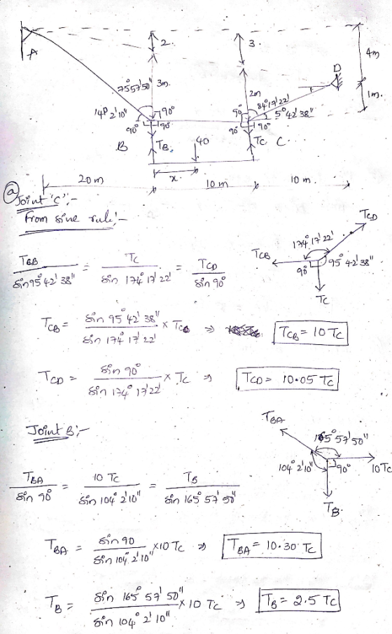
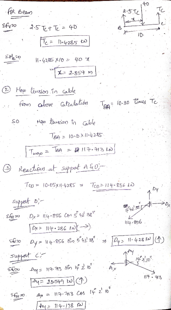
Refer to Figure 2, determine the location of the 40 kN load such that sags at point B and C are 3...
As shown in Figure 8, the structural member (beam) is 7m long, carries a 2 kN point load, a 1.2 kN/m uniformly distribu...
 As shown in Figure 8, the structural member (beam) is 7m long, carries a 2 kN point load, a 1.2 kN/m uniformly distributed load and is supported at points A and B. The beam is constructed from two pieces of steel plate (2 at 80mm x 8mm) that are welded together with 3mm welds. Section properties for the beam are also listed. Given the support reactions as RAv 5.8 kN and RBv 2.2 kN, as well as the shear force...
A loaded beam with a pin support at B and a rller support at C is shown in Figure 1. The applied loads on the bea...
 A loaded beam with a pin support at B and a rller support at C is shown in Figure 1. The applied loads on the beam are: an anti-clockwise point moment at A, a variably distributed load between B and C, and a clockwise point moment at D g kN/m f kNm h kN m A C 4 m 2 m 2 m Figure 1 The magnitude of the anti-clockwise point moment f in units of kN'm can be found...
Problem 1 The rigid structure shown in the figure below is loaded with a concentric couple...
 Problem 1 The rigid structure shown in the figure below is loaded with a concentric couple applied at H of 75 kNm and a concentric horizontal force of 40 kN. A distributed load spans from point D through E with minimum amplitude of 10 kN/m and a maximum of 30 kN/m, respectively. The structure is externally supported by a roller at A, the cable BC and a pin at G. Please do the following: 1. Draw a neat Free Body...
QI A cantilever beam carries a horizontal point load of 100 kN at its end, as...
 QI A cantilever beam carries a horizontal point load of 100 kN at its end, as shown in Figure Q1 (a). In this case, the self weight of the beam must be included. The beam is made from a square box section with a width of b and a depth of b (refer to Figure Q1 (b)). The density of the beam is 20 kN/m and the maximum allowable longitudinal stress of the beam is 200 N/mm². Figure QI (a)...
Q1 A cantilever beam carries a horizontal point load P of 100 kN at its end,...
 Q1 A cantilever beam carries a horizontal point load P of 100 kN at its end, as shown in Figure Q1 (a). In this case, the self weight of the beam must be included. The beam is made from a square box section with a width of b and a depth of b (refer to Figure Q1 (b)). The density of the beam is 20 kN/m² and the maximum allowable longitudinal stress of the beam is 200 N/mm2.K b P=...
Please solve number 2. 2. The beam shown in Figure 1 is used...upport a dead load...
 Please solve number 2.
2. The beam shown in Figure 1 is used...upport a dead load of 500 kN/m, and concentrated live load of 10 KN. Determine the 2.1 the maximum positive (upward) reaction at B, 2.2 the maximum positive shear at C, and 2.3 the maximum positive moment at D. 3. Determine the maximum positive shear and moment at point C due to series of concentrated moving loads shown in the Figure below. ESTAURATION ELEUCO2K5k4k DLOU bent SOSO SEBEUS...
Please solve number 2.
2. The beam shown in Figure 1 is used...upport a dead load of 500 kN/m, and concentrated live load of 10 KN. Determine the 2.1 the maximum positive (upward) reaction at B, 2.2 the maximum positive shear at C, and 2.3 the maximum positive moment at D. 3. Determine the maximum positive shear and moment at point C due to series of concentrated moving loads shown in the Figure below. ESTAURATION ELEUCO2K5k4k DLOU bent SOSO SEBEUS...
Question 2: A simply supported beam under loading as shown in Figure 1: 1. Draw the influence lines of the bending moment and shear force at point C (L/4) Using the influence lines to determine t...
 Question 2: A simply supported beam under loading as shown in Figure 1: 1. Draw the influence lines of the bending moment and shear force at point C (L/4) Using the influence lines to determine the bending moment and shear force at section C due to the loading as shown in the figure. 2. 3. There is a distributed live load (w#2.5kN/m) which can vary the location along the beam. Determine the location of the live loads which create the...
Figure 1 shows a beam is supported by a pin at A and a roller at C. The beam is subjected to point loads 30 kN and 60 kN and a uniformly distributed load of 24 kN/m. Modulus of elasticity, E and momen...
 Figure 1 shows a beam is supported by a pin at A and a roller at
C. The beam is subjected to point
loads 30 kN and 60 kN and a uniformly distributed load of 24 kN/m.
Modulus of elasticity, E and
moment of inertia, I for all members are 205 kN/mm2 and 195 x 106
mm4, respectively. By using
Virtual Work method,
(a) determine the slope at B. (1.801 mrad)
(b) determine the deflection at B and D. (2.4...
Figure 1 shows a beam is supported by a pin at A and a roller at
C. The beam is subjected to point
loads 30 kN and 60 kN and a uniformly distributed load of 24 kN/m.
Modulus of elasticity, E and
moment of inertia, I for all members are 205 kN/mm2 and 195 x 106
mm4, respectively. By using
Virtual Work method,
(a) determine the slope at B. (1.801 mrad)
(b) determine the deflection at B and D. (2.4...
STATIC In the energy transmission line shown in the figure, 20 (kN / m) BC cable...
 STATIC In the energy transmission line shown in the figure, 20 (kN / m) BC cable along the AB cable horizontal opening is loaded with 10 (kN / m) uniformly distributed load along the horizontal opening. Calculate the greatest cable strength and B support reactions occurring in the AB cable. 20kN/m 10 kN/m 7,5m 5m A X 150m * 100+
8.2.8. Use integration to determine the point load and its location (centroid) that are equivalent to...
 8.2.8. Use integration to determine the point load and its location (centroid) that are equivalent to the line load in E8.2.8. 2.0 kN/m 0.5 kN/m l. 10 m 3 m E8.2.8
 As shown in Figure 8, the structural member (beam) is 7m long, carries a 2 kN point load, a 1.2 kN/m uniformly distributed load and is supported at points A and B. The beam is constructed from two pieces of steel plate (2 at 80mm x 8mm) that are welded together with 3mm welds. Section properties for the beam are also listed. Given the support reactions as RAv 5.8 kN and RBv 2.2 kN, as well as the shear force...
 A loaded beam with a pin support at B and a rller support at C is shown in Figure 1. The applied loads on the beam are: an anti-clockwise point moment at A, a variably distributed load between B and C, and a clockwise point moment at D g kN/m f kNm h kN m A C 4 m 2 m 2 m Figure 1 The magnitude of the anti-clockwise point moment f in units of kN'm can be found...
 Problem 1 The rigid structure shown in the figure below is loaded with a concentric couple applied at H of 75 kNm and a concentric horizontal force of 40 kN. A distributed load spans from point D through E with minimum amplitude of 10 kN/m and a maximum of 30 kN/m, respectively. The structure is externally supported by a roller at A, the cable BC and a pin at G. Please do the following: 1. Draw a neat Free Body...
 QI A cantilever beam carries a horizontal point load of 100 kN at its end, as shown in Figure Q1 (a). In this case, the self weight of the beam must be included. The beam is made from a square box section with a width of b and a depth of b (refer to Figure Q1 (b)). The density of the beam is 20 kN/m and the maximum allowable longitudinal stress of the beam is 200 N/mm². Figure QI (a)...
 Q1 A cantilever beam carries a horizontal point load P of 100 kN at its end, as shown in Figure Q1 (a). In this case, the self weight of the beam must be included. The beam is made from a square box section with a width of b and a depth of b (refer to Figure Q1 (b)). The density of the beam is 20 kN/m² and the maximum allowable longitudinal stress of the beam is 200 N/mm2.K b P=...
 Please solve number 2.
2. The beam shown in Figure 1 is used...upport a dead load of 500 kN/m, and concentrated live load of 10 KN. Determine the 2.1 the maximum positive (upward) reaction at B, 2.2 the maximum positive shear at C, and 2.3 the maximum positive moment at D. 3. Determine the maximum positive shear and moment at point C due to series of concentrated moving loads shown in the Figure below. ESTAURATION ELEUCO2K5k4k DLOU bent SOSO SEBEUS...
Please solve number 2.
2. The beam shown in Figure 1 is used...upport a dead load of 500 kN/m, and concentrated live load of 10 KN. Determine the 2.1 the maximum positive (upward) reaction at B, 2.2 the maximum positive shear at C, and 2.3 the maximum positive moment at D. 3. Determine the maximum positive shear and moment at point C due to series of concentrated moving loads shown in the Figure below. ESTAURATION ELEUCO2K5k4k DLOU bent SOSO SEBEUS...
 Question 2: A simply supported beam under loading as shown in Figure 1: 1. Draw the influence lines of the bending moment and shear force at point C (L/4) Using the influence lines to determine the bending moment and shear force at section C due to the loading as shown in the figure. 2. 3. There is a distributed live load (w#2.5kN/m) which can vary the location along the beam. Determine the location of the live loads which create the...
 Figure 1 shows a beam is supported by a pin at A and a roller at
C. The beam is subjected to point
loads 30 kN and 60 kN and a uniformly distributed load of 24 kN/m.
Modulus of elasticity, E and
moment of inertia, I for all members are 205 kN/mm2 and 195 x 106
mm4, respectively. By using
Virtual Work method,
(a) determine the slope at B. (1.801 mrad)
(b) determine the deflection at B and D. (2.4...
Figure 1 shows a beam is supported by a pin at A and a roller at
C. The beam is subjected to point
loads 30 kN and 60 kN and a uniformly distributed load of 24 kN/m.
Modulus of elasticity, E and
moment of inertia, I for all members are 205 kN/mm2 and 195 x 106
mm4, respectively. By using
Virtual Work method,
(a) determine the slope at B. (1.801 mrad)
(b) determine the deflection at B and D. (2.4...
 STATIC In the energy transmission line shown in the figure, 20 (kN / m) BC cable along the AB cable horizontal opening is loaded with 10 (kN / m) uniformly distributed load along the horizontal opening. Calculate the greatest cable strength and B support reactions occurring in the AB cable. 20kN/m 10 kN/m 7,5m 5m A X 150m * 100+
 8.2.8. Use integration to determine the point load and its location (centroid) that are equivalent to the line load in E8.2.8. 2.0 kN/m 0.5 kN/m l. 10 m 3 m E8.2.8
Most questions answered within 3 hours.
-
Where is the error in this code sequence?
String s1 = "Hello";
String s2 = "ello";...
asked 11 months ago -
Financial data for Joel de Paris, Inc., for last year
follow:
Joel de Paris, Inc.
Balance...
asked 11 months ago -
Consider this reaction:
Al2(SO4)3 (aq)+ BaCl3
(aq) Al2Cl6 (aq)- +
3BaSO4(s) . What is the...
asked 11 months ago -
Suppose that Savneet is considering increasing her
recent random sample from 20 car rentals to 40...
asked 11 months ago -
Trucks arrive at an unloading terminal at an average rate of 120
per hour.
Trucks arrive...
asked 11 months ago -
Why are methanol and ethanol completely soluble in water while
octanol is not very little soluble....
asked 11 months ago -
A facilities manager at a university reads in a research report
that the mean amount of...
asked 11 months ago -
When the CuSO4 is rehydrated by adding water to the anhydrous
compound, is this an endothermic...
asked 11 months ago -
A ray of sunlight is passing from diamond into crown glass; the
angle of incidence is...
asked 11 months ago -
A block of mass 0.249 kg is placed on top of a light, vertical
spring of...
asked 11 months ago -
how do the kidneys compensate in the presences of acidosis
a) trigger hyperventilate
b) reserve acid...
asked 11 months ago -
Question 501 pts
The rental rate of capital to the firm increases. Which of the
following...
asked 11 months ago