
Homework Answers

Add Answer to:
5.20 The op amp in the circuit shown in Fig, P5.20 is ideal, Calculate v, when v, equals 3 V b) S...
63 k12 The Op Amp in the circuit shown in Fig. 1 is ideal, 30 k02...
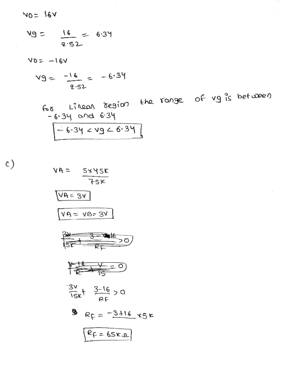
 63 k12 The Op Amp in the circuit shown in Fig. 1 is ideal, 30 k02 12 V 12 k 12 - 12 V + a. Calculate vo when Vg equals 4 V. b. Specify the range of values of vg so that the Op Amp operates in a linear mode. c. Assume that Vg equals 2 V and that the 63 K12 resistor is replaced with a variable resistor. What value of the variable resistor will cause the Op...
5.4 The op amp in the circuit of Fig. P5.19 is ideal. a) What op amp...
 5.4 The op amp in the circuit of Fig. P5.19 is ideal. a) What op amp circuit configuration is this? b) Find in terms of us . c) Find the range of values for e, such that e, does nol saturate and thc op amp remains in its lincar region of operation. Figure P5.19 40 kΩ 10 V 12 kΩ 10 V 1 S1DE
Solve by using basic node-voltage or superposition! The op amp in the circuit of Fig. P5.23...
 Solve by using basic node-voltage or superposition! The op amp in the circuit of Fig. P5.23 is ideal. a) What op amp circuit configuration is this? b) Find vo in terms of vs c) Find the range of values for such that does not saturate and the op amp remains in its linear region of operation. Figure P5.23 96 kΩ 24 kΩ 10 V 16 kΩ 10V 24 kΩ
The op amp in the circuit shown below is ideal. The adjustable resistor has a maximum...
 The op amp in the circuit shown below is ideal. The adjustable resistor has a maximum value of 100 k Ohm , and alpha is restricted to the range of 0.2 a 1.0. Calculate the range of v0 if vg = 40mV. If alpha is not restricted, at what value of alpha will the op amp saturate?
The op amp in the circuit in Figure below is ideal. a) (3pts) Calculate vo if...
 The op amp in the circuit in Figure below is ideal. a) (3pts) Calculate vo if va=1 V and vh=2.5 V. b) (3pts) Calculate vo if va =2.5 V and v5 = 1V f) (2pts) If Vb = 2.5 V, specify the range of va such that the amplifier does not saturate. 40 k N16V 2k1 totx 16V v.210k
The op amp in the circuit in (Figure 1) is ideal. Suppose R-16 kΩ Part A...
 The op amp in the circuit in (Figure 1) is ideal. Suppose R-16 kΩ Part A What op amp circuit configuration is this? O This circuit is an example of the inverting amplifier o This circuit is an example of the non-inverting amplifier Submit Request Answer ▼ Part B Find vo in terms of vs Express your answer in terms of vs 07 Figure 1 of 1 > Submit Request Answer Part C 56 kΩ Find the minimum value of...
Ch 5 Analysis of Ideal Op Amp Circuits 1 of 11> Part B Ideal op amp...
 Ch 5 Analysis of Ideal Op Amp Circuits 1 of 11> Part B Ideal op amp circuits with a voltage source: part 2 Learning Goal: For the circuit shown (Figure 1), determine the range (i.e., maximum and minimum values) of V so that the op amp operates in the linear region. Assume that R1-5 ? . R2-1 kN. R3-60 ? , and V,-15 V To analyze circuits that contain op amps using the ideal op amp assumptions. Express your answer...
Part C - Saturation of a summing op amp circuit For the circuit shown(Figure 2), determine...
 Part C - Saturation of a summing op amp circuit
For the circuit shown(Figure 2), determine the range (i.e.,
maximum and minimum values) of V1V1 such that the op amp operates
in the linear region. Assume that R1 = 5.0 kΩ , R2 = 8.2 kΩ , R3 =
8.2 kΩ , RF = 180 kΩ , V2 = 10 mV, V3 = 60 mV , and VCC = 15 V
.
Express your answer to three significant figures separated...
Part C - Saturation of a summing op amp circuit
For the circuit shown(Figure 2), determine the range (i.e.,
maximum and minimum values) of V1V1 such that the op amp operates
in the linear region. Assume that R1 = 5.0 kΩ , R2 = 8.2 kΩ , R3 =
8.2 kΩ , RF = 180 kΩ , V2 = 10 mV, V3 = 60 mV , and VCC = 15 V
.
Express your answer to three significant figures separated...
Problem 1) [15 marks] The gain of the dual-op-axap instrumentation amplifier shown in Fig. 1 can be adjusted by the variable resistor Ro. The op-amps are ideal. atu Fig. 1 a)Show that v.-2(1 RG )...
 Problem 1) [15 marks] The gain of the dual-op-axap instrumentation amplifier shown in Fig. 1 can be adjusted by the variable resistor Ro. The op-amps are ideal. atu Fig. 1 a)Show that v.-2(1 RG )(v2-v.). b Specify suitable components to have a variable gain from 10 to 100 V/V. Problem 2) [15 marks] a) Design an op-amp limiter circuit for amplitude control with the transfer characteristic of Fig. 2(a). Use +-15V DC sources to power the circuit. Assume Vo-0.7 V...
5-4: The following circuit contains an ideal op-amp. The variable feedback resistor Re is adjusted until...
 5-4: The following circuit contains an ideal op-amp. The variable feedback resistor Re is adjusted until the op-amp saturates. Determine the value of R Re 1.6 kΩ 9 V 7.5 kΩ 9 V 18 V 1.5 kΩ 5-5: The following circuit contains an ideal op-amp. Assume Va = 1V, VB-1.5V, and Vc =-4V. Find the value of Vo. 220 kΩ 44 kΩ 10 V + 27.5 kΩ 80 k2 10 V 0a D)
 63 k12 The Op Amp in the circuit shown in Fig. 1 is ideal, 30 k02 12 V 12 k 12 - 12 V + a. Calculate vo when Vg equals 4 V. b. Specify the range of values of vg so that the Op Amp operates in a linear mode. c. Assume that Vg equals 2 V and that the 63 K12 resistor is replaced with a variable resistor. What value of the variable resistor will cause the Op...
 5.4 The op amp in the circuit of Fig. P5.19 is ideal. a) What op amp circuit configuration is this? b) Find in terms of us . c) Find the range of values for e, such that e, does nol saturate and thc op amp remains in its lincar region of operation. Figure P5.19 40 kΩ 10 V 12 kΩ 10 V 1 S1DE
 Solve by using basic node-voltage or superposition! The op amp in the circuit of Fig. P5.23 is ideal. a) What op amp circuit configuration is this? b) Find vo in terms of vs c) Find the range of values for such that does not saturate and the op amp remains in its linear region of operation. Figure P5.23 96 kΩ 24 kΩ 10 V 16 kΩ 10V 24 kΩ
 The op amp in the circuit shown below is ideal. The adjustable resistor has a maximum value of 100 k Ohm , and alpha is restricted to the range of 0.2 a 1.0. Calculate the range of v0 if vg = 40mV. If alpha is not restricted, at what value of alpha will the op amp saturate?
 The op amp in the circuit in Figure below is ideal. a) (3pts) Calculate vo if va=1 V and vh=2.5 V. b) (3pts) Calculate vo if va =2.5 V and v5 = 1V f) (2pts) If Vb = 2.5 V, specify the range of va such that the amplifier does not saturate. 40 k N16V 2k1 totx 16V v.210k
 The op amp in the circuit in (Figure 1) is ideal. Suppose R-16 kΩ Part A What op amp circuit configuration is this? O This circuit is an example of the inverting amplifier o This circuit is an example of the non-inverting amplifier Submit Request Answer ▼ Part B Find vo in terms of vs Express your answer in terms of vs 07 Figure 1 of 1 > Submit Request Answer Part C 56 kΩ Find the minimum value of...
 Ch 5 Analysis of Ideal Op Amp Circuits 1 of 11> Part B Ideal op amp circuits with a voltage source: part 2 Learning Goal: For the circuit shown (Figure 1), determine the range (i.e., maximum and minimum values) of V so that the op amp operates in the linear region. Assume that R1-5 ? . R2-1 kN. R3-60 ? , and V,-15 V To analyze circuits that contain op amps using the ideal op amp assumptions. Express your answer...
 Part C - Saturation of a summing op amp circuit
For the circuit shown(Figure 2), determine the range (i.e.,
maximum and minimum values) of V1V1 such that the op amp operates
in the linear region. Assume that R1 = 5.0 kΩ , R2 = 8.2 kΩ , R3 =
8.2 kΩ , RF = 180 kΩ , V2 = 10 mV, V3 = 60 mV , and VCC = 15 V
.
Express your answer to three significant figures separated...
Part C - Saturation of a summing op amp circuit
For the circuit shown(Figure 2), determine the range (i.e.,
maximum and minimum values) of V1V1 such that the op amp operates
in the linear region. Assume that R1 = 5.0 kΩ , R2 = 8.2 kΩ , R3 =
8.2 kΩ , RF = 180 kΩ , V2 = 10 mV, V3 = 60 mV , and VCC = 15 V
.
Express your answer to three significant figures separated...
 Problem 1) [15 marks] The gain of the dual-op-axap instrumentation amplifier shown in Fig. 1 can be adjusted by the variable resistor Ro. The op-amps are ideal. atu Fig. 1 a)Show that v.-2(1 RG )(v2-v.). b Specify suitable components to have a variable gain from 10 to 100 V/V. Problem 2) [15 marks] a) Design an op-amp limiter circuit for amplitude control with the transfer characteristic of Fig. 2(a). Use +-15V DC sources to power the circuit. Assume Vo-0.7 V...
 5-4: The following circuit contains an ideal op-amp. The variable feedback resistor Re is adjusted until the op-amp saturates. Determine the value of R Re 1.6 kΩ 9 V 7.5 kΩ 9 V 18 V 1.5 kΩ 5-5: The following circuit contains an ideal op-amp. Assume Va = 1V, VB-1.5V, and Vc =-4V. Find the value of Vo. 220 kΩ 44 kΩ 10 V + 27.5 kΩ 80 k2 10 V 0a D)
Most questions answered within 3 hours.
-
Where is the error in this code sequence?
String s1 = "Hello";
String s2 = "ello";...
asked 11 months ago -
Financial data for Joel de Paris, Inc., for last year
follow:
Joel de Paris, Inc.
Balance...
asked 11 months ago -
Consider this reaction:
Al2(SO4)3 (aq)+ BaCl3
(aq) Al2Cl6 (aq)- +
3BaSO4(s) . What is the...
asked 11 months ago -
Suppose that Savneet is considering increasing her
recent random sample from 20 car rentals to 40...
asked 11 months ago -
Trucks arrive at an unloading terminal at an average rate of 120
per hour.
Trucks arrive...
asked 11 months ago -
Why are methanol and ethanol completely soluble in water while
octanol is not very little soluble....
asked 11 months ago -
A facilities manager at a university reads in a research report
that the mean amount of...
asked 11 months ago -
When the CuSO4 is rehydrated by adding water to the anhydrous
compound, is this an endothermic...
asked 11 months ago -
A ray of sunlight is passing from diamond into crown glass; the
angle of incidence is...
asked 11 months ago -
A block of mass 0.249 kg is placed on top of a light, vertical
spring of...
asked 11 months ago -
how do the kidneys compensate in the presences of acidosis
a) trigger hyperventilate
b) reserve acid...
asked 11 months ago -
Question 501 pts
The rental rate of capital to the firm increases. Which of the
following...
asked 11 months ago