If the oscilloscope in your experiment were measuring the potential difference across the resisto...
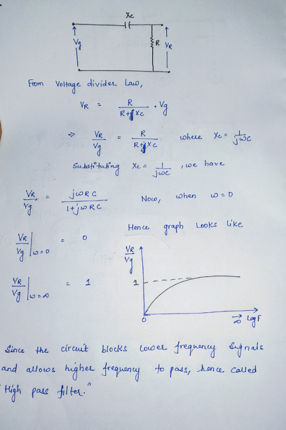
If the oscilloscope in your experiment were measuring the potential difference across the resistor instead of the capacitor and you plotted Vres/Vgen vs. log(frequency), what would you expect the plot to look like? Give a qualitative explanation for the behavior of this plot. Why is this set-up referred to as a “high pass filter”?
Homework Answers
Add Answer to:
If the oscilloscope in your experiment were measuring the potential difference across the resisto...
-You calculate the impedance of a single element in the circuit. The impedance is j25. What...
-You calculate the impedance of a single element in the circuit. The impedance is j25. What is the polar form? (25 angle -90 is incorrect, probably just the angle is incorrect not sure) -You are using a 10x oscilloscope probe on a circuit. The alligator clip of the probe connects to the: (A is incorrect, I think it is D) a) Vout of the circuit b) Vin of the circuit c) Negative side of the resistor d) Ground reference e)...
What are the Equilibrium voltages of the capacitor and the resistor when the function generator v...
 What are the Equilibrium voltages of the capacitor and the
resistor when the function generator voltage is +v0? Is this what
you observe on your oscilloscope sketches?
what are the equilibrium voltages of the capacitor and the resistor when the function generator voltage is ± you observe on your oscilloscope sketches? ? Is this what An RC circuit consists of a resistor connected to a capacitor. There may also be a fixed power supply, depending on whether the capacitor is...
What are the Equilibrium voltages of the capacitor and the
resistor when the function generator voltage is +v0? Is this what
you observe on your oscilloscope sketches?
what are the equilibrium voltages of the capacitor and the resistor when the function generator voltage is ± you observe on your oscilloscope sketches? ? Is this what An RC circuit consists of a resistor connected to a capacitor. There may also be a fixed power supply, depending on whether the capacitor is...
1. In this class and in other physics lab classes you will often use oscilloscopes to...
 1. In this class and in other physics lab classes you will often use oscilloscopes to look at signal that change in time. Below is a sinusoidal AC signal on an oscilloscope screen. The vertical axis is set to 10 mV/division and the horizontal axis is set to 50 ms/division For the signal shown, what is the: a. Average voltage? b. Peak voltage? c. Peak-to-peak voltage? d. RMS voltage? e. Period? f. Frequency? g. If you were to write an...
What is the answer to question 23.1? 23.1 Active low-pass filter You can make a low-pass...
 What is the answer to question
23.1?
23.1 Active low-pass filter You can make a low-pass filter by putting a capacitor Cr and resistor Rf in parallel for Zj as shown in Figure 23.1. At low frequencies (well below the corner frequency), the feedback impedance is approximately Rf and the gain of a non-inverting amplifier is is 1 +R//R,. At high frequencies (well above the corner frequency),the impedance is approx- imately 1/(jwCs), and the gain of a non-inverting amplifier is...
What is the answer to question
23.1?
23.1 Active low-pass filter You can make a low-pass filter by putting a capacitor Cr and resistor Rf in parallel for Zj as shown in Figure 23.1. At low frequencies (well below the corner frequency), the feedback impedance is approximately Rf and the gain of a non-inverting amplifier is is 1 +R//R,. At high frequencies (well above the corner frequency),the impedance is approx- imately 1/(jwCs), and the gain of a non-inverting amplifier is...
1. Read the laboratory supplement entitled “Frequency Response". 2. Read the remainder of this handout. 3....
 1. Read the laboratory supplement entitled “Frequency Response". 2. Read the remainder of this handout. 3. In Multisim, build the circuit shown in Figure 1 with C=0.22 uF and R = 2.2 k12. This circuit looks like a simple voltage divider except that one of the resistors is replaced by a capacitor. Il Figure 1: RC network. F Set up Vin to be a 1 Vpp sinusoid with 0 VDC Offset using a function generator. 2. Connect the oscilloscope in...
One or two sentence answers are fine. But please be clear with explanations. For each statement,...
One or two sentence answers are fine. But please be clear with explanations. For each statement, decide whether it is always true, always false or true in certain circumstances. State which case applies to the statement, describing why you chose the answer you did and cite an experiment or principle of Physics which supports` your claim. [1] In a capacitor in an AC circuit, the electric field leads the current. [2] The impedance of a capacitor increases with frequency. [3]...
PLEASE ANSWER VERY QUICKLY!! I RATE HIGH!! The experiment is on RC circuits and the aim is to determine the time constant. Your group sets up the circuit with a resistor R and a capacitor C conne...
 PLEASE ANSWER VERY QUICKLY!! I RATE HIGH!!
The experiment is on RC circuits and the aim is to determine the time constant. Your group sets up the circuit with a resistor R and a capacitor C connected to a switch and an ideal battery (E). The circuit diagram is shown in the figure. You close the switch at time Os and the voltage across the capacitor Ve and current I in the ammeter are recorded in a spreadsheet using a...
PLEASE ANSWER VERY QUICKLY!! I RATE HIGH!!
The experiment is on RC circuits and the aim is to determine the time constant. Your group sets up the circuit with a resistor R and a capacitor C connected to a switch and an ideal battery (E). The circuit diagram is shown in the figure. You close the switch at time Os and the voltage across the capacitor Ve and current I in the ammeter are recorded in a spreadsheet using a...
Experiment 7 - The Resistor Capacitor Circuit Learning Objectives: Understand the short and long time behavior...
 Experiment 7 - The Resistor Capacitor Circuit Learning Objectives: Understand the short and long time behavior of circuits containing capacitors. Understand the and the mathematical relationshin between the current through the circuit as a function time, resistance, capacitance, and potential difference 1. Understanding the models for the behavior of a capacitor in a circuit A capacitor is a device that stores energy in a circuit as potential energy in an electric field. In the simple circuit drawn on the night,...
need help graphing this to make it a "voltage across the resistor vs. frequency" please show...
 need help graphing this to make it a "voltage across the
resistor vs. frequency" please show work thank you
how is it in complete?
EXPERIMENT 7. RLC SERIES CIRCUIT NAN PART DATE 3/ylis LA ROCEDURE A: REACTANCES AND POTENTIALs Resistance of inductor R Resistance of L & N box Capacitance of Cenco box Power Supply Voltage from DMNM Voltage across the capacitor V 500 0.10 3.00 S2 volts volts Voltage across the inductor V evots Voltage across L & N...
need help graphing this to make it a "voltage across the
resistor vs. frequency" please show work thank you
how is it in complete?
EXPERIMENT 7. RLC SERIES CIRCUIT NAN PART DATE 3/ylis LA ROCEDURE A: REACTANCES AND POTENTIALs Resistance of inductor R Resistance of L & N box Capacitance of Cenco box Power Supply Voltage from DMNM Voltage across the capacitor V 500 0.10 3.00 S2 volts volts Voltage across the inductor V evots Voltage across L & N...
We calculated the capacticance of our capacitior in farads and we have to compare it to...
 We
calculated the capacticance of our capacitior in farads and we have
to compare it to the listed capacitance of the capacitor as shown
in the picture. When we do percent difference we get 200%... where
did I mess up? That can't be right. The resistance of our resistor
is 12970 ohms. Please explain this like you were talking to a
child.
Amicon 26936KO (M) 2000 F25V 81-POLAR NPS wire leads of the resistor to the table the body of...
We
calculated the capacticance of our capacitior in farads and we have
to compare it to the listed capacitance of the capacitor as shown
in the picture. When we do percent difference we get 200%... where
did I mess up? That can't be right. The resistance of our resistor
is 12970 ohms. Please explain this like you were talking to a
child.
Amicon 26936KO (M) 2000 F25V 81-POLAR NPS wire leads of the resistor to the table the body of...
 What are the Equilibrium voltages of the capacitor and the
resistor when the function generator voltage is +v0? Is this what
you observe on your oscilloscope sketches?
what are the equilibrium voltages of the capacitor and the resistor when the function generator voltage is ± you observe on your oscilloscope sketches? ? Is this what An RC circuit consists of a resistor connected to a capacitor. There may also be a fixed power supply, depending on whether the capacitor is...
What are the Equilibrium voltages of the capacitor and the
resistor when the function generator voltage is +v0? Is this what
you observe on your oscilloscope sketches?
what are the equilibrium voltages of the capacitor and the resistor when the function generator voltage is ± you observe on your oscilloscope sketches? ? Is this what An RC circuit consists of a resistor connected to a capacitor. There may also be a fixed power supply, depending on whether the capacitor is...
 1. In this class and in other physics lab classes you will often use oscilloscopes to look at signal that change in time. Below is a sinusoidal AC signal on an oscilloscope screen. The vertical axis is set to 10 mV/division and the horizontal axis is set to 50 ms/division For the signal shown, what is the: a. Average voltage? b. Peak voltage? c. Peak-to-peak voltage? d. RMS voltage? e. Period? f. Frequency? g. If you were to write an...
 What is the answer to question
23.1?
23.1 Active low-pass filter You can make a low-pass filter by putting a capacitor Cr and resistor Rf in parallel for Zj as shown in Figure 23.1. At low frequencies (well below the corner frequency), the feedback impedance is approximately Rf and the gain of a non-inverting amplifier is is 1 +R//R,. At high frequencies (well above the corner frequency),the impedance is approx- imately 1/(jwCs), and the gain of a non-inverting amplifier is...
What is the answer to question
23.1?
23.1 Active low-pass filter You can make a low-pass filter by putting a capacitor Cr and resistor Rf in parallel for Zj as shown in Figure 23.1. At low frequencies (well below the corner frequency), the feedback impedance is approximately Rf and the gain of a non-inverting amplifier is is 1 +R//R,. At high frequencies (well above the corner frequency),the impedance is approx- imately 1/(jwCs), and the gain of a non-inverting amplifier is...
 1. Read the laboratory supplement entitled “Frequency Response". 2. Read the remainder of this handout. 3. In Multisim, build the circuit shown in Figure 1 with C=0.22 uF and R = 2.2 k12. This circuit looks like a simple voltage divider except that one of the resistors is replaced by a capacitor. Il Figure 1: RC network. F Set up Vin to be a 1 Vpp sinusoid with 0 VDC Offset using a function generator. 2. Connect the oscilloscope in...
 PLEASE ANSWER VERY QUICKLY!! I RATE HIGH!!
The experiment is on RC circuits and the aim is to determine the time constant. Your group sets up the circuit with a resistor R and a capacitor C connected to a switch and an ideal battery (E). The circuit diagram is shown in the figure. You close the switch at time Os and the voltage across the capacitor Ve and current I in the ammeter are recorded in a spreadsheet using a...
PLEASE ANSWER VERY QUICKLY!! I RATE HIGH!!
The experiment is on RC circuits and the aim is to determine the time constant. Your group sets up the circuit with a resistor R and a capacitor C connected to a switch and an ideal battery (E). The circuit diagram is shown in the figure. You close the switch at time Os and the voltage across the capacitor Ve and current I in the ammeter are recorded in a spreadsheet using a...
 Experiment 7 - The Resistor Capacitor Circuit Learning Objectives: Understand the short and long time behavior of circuits containing capacitors. Understand the and the mathematical relationshin between the current through the circuit as a function time, resistance, capacitance, and potential difference 1. Understanding the models for the behavior of a capacitor in a circuit A capacitor is a device that stores energy in a circuit as potential energy in an electric field. In the simple circuit drawn on the night,...
 need help graphing this to make it a "voltage across the
resistor vs. frequency" please show work thank you
how is it in complete?
EXPERIMENT 7. RLC SERIES CIRCUIT NAN PART DATE 3/ylis LA ROCEDURE A: REACTANCES AND POTENTIALs Resistance of inductor R Resistance of L & N box Capacitance of Cenco box Power Supply Voltage from DMNM Voltage across the capacitor V 500 0.10 3.00 S2 volts volts Voltage across the inductor V evots Voltage across L & N...
need help graphing this to make it a "voltage across the
resistor vs. frequency" please show work thank you
how is it in complete?
EXPERIMENT 7. RLC SERIES CIRCUIT NAN PART DATE 3/ylis LA ROCEDURE A: REACTANCES AND POTENTIALs Resistance of inductor R Resistance of L & N box Capacitance of Cenco box Power Supply Voltage from DMNM Voltage across the capacitor V 500 0.10 3.00 S2 volts volts Voltage across the inductor V evots Voltage across L & N...
 We
calculated the capacticance of our capacitior in farads and we have
to compare it to the listed capacitance of the capacitor as shown
in the picture. When we do percent difference we get 200%... where
did I mess up? That can't be right. The resistance of our resistor
is 12970 ohms. Please explain this like you were talking to a
child.
Amicon 26936KO (M) 2000 F25V 81-POLAR NPS wire leads of the resistor to the table the body of...
We
calculated the capacticance of our capacitior in farads and we have
to compare it to the listed capacitance of the capacitor as shown
in the picture. When we do percent difference we get 200%... where
did I mess up? That can't be right. The resistance of our resistor
is 12970 ohms. Please explain this like you were talking to a
child.
Amicon 26936KO (M) 2000 F25V 81-POLAR NPS wire leads of the resistor to the table the body of...
Most questions answered within 3 hours.
-
Where is the error in this code sequence?
String s1 = "Hello";
String s2 = "ello";...
asked 11 months ago -
Financial data for Joel de Paris, Inc., for last year
follow:
Joel de Paris, Inc.
Balance...
asked 11 months ago -
Consider this reaction:
Al2(SO4)3 (aq)+ BaCl3
(aq) Al2Cl6 (aq)- +
3BaSO4(s) . What is the...
asked 11 months ago -
Suppose that Savneet is considering increasing her
recent random sample from 20 car rentals to 40...
asked 11 months ago -
Trucks arrive at an unloading terminal at an average rate of 120
per hour.
Trucks arrive...
asked 11 months ago -
Why are methanol and ethanol completely soluble in water while
octanol is not very little soluble....
asked 11 months ago -
A facilities manager at a university reads in a research report
that the mean amount of...
asked 11 months ago -
When the CuSO4 is rehydrated by adding water to the anhydrous
compound, is this an endothermic...
asked 11 months ago -
A ray of sunlight is passing from diamond into crown glass; the
angle of incidence is...
asked 11 months ago -
A block of mass 0.249 kg is placed on top of a light, vertical
spring of...
asked 11 months ago -
how do the kidneys compensate in the presences of acidosis
a) trigger hyperventilate
b) reserve acid...
asked 11 months ago -
Question 501 pts
The rental rate of capital to the firm increases. Which of the
following...
asked 11 months ago