
Homework Answers
Hope it helps you out.
In case any doubt please feel free to ask.
I will be happy to help you.
Thanks!!
Add Answer to:
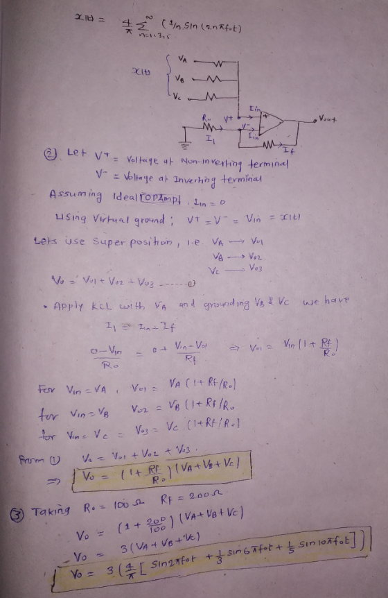
1. Using Fourier series expansion, it can be shown that a square wave, x(0), with frequency, fo. can be decomposed into...
Note: Show all your work to get partial credit. 1. Consider a non-inverting operational amplifier. Let...
 Note: Show all your work to get partial credit. 1. Consider a non-inverting operational amplifier. Let us assume that the feedback resister Rr 10K. Find the input resister Rin to get the voltage gain of 11. (5 points) 2. Calculate the output voltage of the summing amplifier shown in Fig. 1. (10 points) R1 Rf R2 Vout R3 Fig. 1 Summing Amplifier
Problem # 3 For the summing opamp circuit, assume that the opamp is powered with +15V and-15V. Th...
 Problem # 3 For the summing opamp circuit, assume that the opamp is powered with +15V and-15V. The input voltages are VI and V2 and the output voltage is Vout. Rf 15 V U1 R1 R2 Vout 741 V2 (A -15 V 1. Find the relation between the output Vout and the inputs VI and V2 2. Assume that RI-2kS2, R2-3 ㏀ and Rf-6kS2, Vin is a sinewave with viinpp-2V, V2DC- IV, plot Vin() and Vout(0) 3. Assume that you...
Problem 3: a) For the inverting amplifier designed using low noise amplifier AD743 shown on the...
Problem 3: a) For the inverting amplifier designed using low noise amplifier AD743 shown on the bottom of the page with Ri=10kOhm and Rf=220kOhm, what should be the value of the resistor connected to the non-inverting input (R2) to minimize the output offset due to input bias current? b.) Even if the R2 value you calculated is used, could there be an output offset due to a difference between the two input bias currents? What is the maximum value of...
Laboratory 1: operation amplifier characteristics A. Objectives: 1. To study the basic characteri...
 thanks
Laboratory 1: operation amplifier characteristics A. Objectives: 1. To study the basic characteristics of an operational amplifier 2. To study the bias circuit of an operational amplifier B. Apparatus: 1. DC Power supply 2. Experimental board and corresponding components 3. Electronic calculator (prepared by students) 4. Digital camera (prepared by students for photo taking of the experimental results) 5. Laptop computer with the software PicoScope 6 and Microsoft Word installed. 6. PicoScope PC Oscilloscope and its accessories. 7. Multimeter...
thanks
Laboratory 1: operation amplifier characteristics A. Objectives: 1. To study the basic characteristics of an operational amplifier 2. To study the bias circuit of an operational amplifier B. Apparatus: 1. DC Power supply 2. Experimental board and corresponding components 3. Electronic calculator (prepared by students) 4. Digital camera (prepared by students for photo taking of the experimental results) 5. Laptop computer with the software PicoScope 6 and Microsoft Word installed. 6. PicoScope PC Oscilloscope and its accessories. 7. Multimeter...
Inverting Amplifier Figure 4.2 shows the fundamental configuration of Op-Amp in which it is used as...
 Inverting Amplifier Figure 4.2 shows the fundamental configuration of Op-Amp in which it is used as an inverting amplifier. In this configuration the ratio, R2/R1 completely controls the effective gain of the amplifier and it can be verified that the output voltage is equal to Vo = - (R2/R1)Vin R2 100K Q-10V R1 Vinow 20K 1 2 7 V Vo 3 -10v Figure 4.2 Part 1 - Inverting Amp: Procedure 1. Construct the circuit of figure 4.2 using Op-Amp IC...
Problem 1) [15 marks] The gain of the dual-op-axap instrumentation amplifier shown in Fig. 1 can be adjusted by the variable resistor Ro. The op-amps are ideal. atu Fig. 1 a)Show that v.-2(1 RG )...
 Problem 1) [15 marks] The gain of the dual-op-axap instrumentation amplifier shown in Fig. 1 can be adjusted by the variable resistor Ro. The op-amps are ideal. atu Fig. 1 a)Show that v.-2(1 RG )(v2-v.). b Specify suitable components to have a variable gain from 10 to 100 V/V. Problem 2) [15 marks] a) Design an op-amp limiter circuit for amplitude control with the transfer characteristic of Fig. 2(a). Use +-15V DC sources to power the circuit. Assume Vo-0.7 V...
need help for d,e,f OP-Amp Circuit R-20k Fig 1 1. Design an operational amplifier circuit using an LM741 op-amp an...
 need help for d,e,f
OP-Amp Circuit R-20k Fig 1 1. Design an operational amplifier circuit using an LM741 op-amp and a 10k the diagram shown in Fig 1 to produce the output voltage feedback resistor that represents Clearly write your ID number in Table 1 Table 1 Your ID Number 3775。73 . Set up the roquired gain numbers as follows and write them in Table 2 Ai- the last digit of your ID number+5 A2-the 2ed last digit of your...
need help for d,e,f
OP-Amp Circuit R-20k Fig 1 1. Design an operational amplifier circuit using an LM741 op-amp and a 10k the diagram shown in Fig 1 to produce the output voltage feedback resistor that represents Clearly write your ID number in Table 1 Table 1 Your ID Number 3775。73 . Set up the roquired gain numbers as follows and write them in Table 2 Ai- the last digit of your ID number+5 A2-the 2ed last digit of your...
solve 2.40 a,b,c, e using Fourier series. 2.40 part a,b,c,e 2.40 Consider the continuous-time signals depicted in Fig. P2.40. Evaluate the following convolution integrals: (a) m(t) x(t) y(t) (...
 solve 2.40 a,b,c, e using Fourier series.
2.40 part a,b,c,e 2.40 Consider the continuous-time signals depicted in Fig. P2.40. Evaluate the following convolution integrals: (a) m(t) x(t) y(t) (b) m(t)x(t)z(t) (c) m(t) x(t) ft) (d) m(t) x(t) a(t) (e) m(t)y(t) z(t) (f) m(t) -y(t) w(t) (g) m(t) y(t)g(t) (h) m(t)y(t) c(t) (i) m(t) z(t) f(t) (j) m(t) z(t) g(t) (k) m(t) z(t)b(t) (1) m(t) w(t) g(t) (m) m(t) w(t) a(t) (n) m(t) f(t) g(t (o) m(t) fo) . do) (p)...
solve 2.40 a,b,c, e using Fourier series.
2.40 part a,b,c,e 2.40 Consider the continuous-time signals depicted in Fig. P2.40. Evaluate the following convolution integrals: (a) m(t) x(t) y(t) (b) m(t)x(t)z(t) (c) m(t) x(t) ft) (d) m(t) x(t) a(t) (e) m(t)y(t) z(t) (f) m(t) -y(t) w(t) (g) m(t) y(t)g(t) (h) m(t)y(t) c(t) (i) m(t) z(t) f(t) (j) m(t) z(t) g(t) (k) m(t) z(t)b(t) (1) m(t) w(t) g(t) (m) m(t) w(t) a(t) (n) m(t) f(t) g(t (o) m(t) fo) . do) (p)...
Vout should be a sinusoid signal of 12Vp-p Dc voltage to uA741 : +/-8.5V Please simulate...
 Vout should be a sinusoid signal of 12Vp-p
Dc voltage to uA741 : +/-8.5V
Please simulate as well
please help, im completely lost on this
this is all of the information
Experiment 5. RC Sinusoidal Oscillators PURPOSE: This laboratory provides an introduction to the background, analysis and design of sinusoidal oscillators using RC feedback networks and active devices to achieve the criteria for continuous oscillations to occur. EQUIPMENT REQUIRED : 1 Operational amplifier u.A741 1 CEU development station Resistors and...
Vout should be a sinusoid signal of 12Vp-p
Dc voltage to uA741 : +/-8.5V
Please simulate as well
please help, im completely lost on this
this is all of the information
Experiment 5. RC Sinusoidal Oscillators PURPOSE: This laboratory provides an introduction to the background, analysis and design of sinusoidal oscillators using RC feedback networks and active devices to achieve the criteria for continuous oscillations to occur. EQUIPMENT REQUIRED : 1 Operational amplifier u.A741 1 CEU development station Resistors and...
 Note: Show all your work to get partial credit. 1. Consider a non-inverting operational amplifier. Let us assume that the feedback resister Rr 10K. Find the input resister Rin to get the voltage gain of 11. (5 points) 2. Calculate the output voltage of the summing amplifier shown in Fig. 1. (10 points) R1 Rf R2 Vout R3 Fig. 1 Summing Amplifier
 Problem # 3 For the summing opamp circuit, assume that the opamp is powered with +15V and-15V. The input voltages are VI and V2 and the output voltage is Vout. Rf 15 V U1 R1 R2 Vout 741 V2 (A -15 V 1. Find the relation between the output Vout and the inputs VI and V2 2. Assume that RI-2kS2, R2-3 ㏀ and Rf-6kS2, Vin is a sinewave with viinpp-2V, V2DC- IV, plot Vin() and Vout(0) 3. Assume that you...
 thanks
Laboratory 1: operation amplifier characteristics A. Objectives: 1. To study the basic characteristics of an operational amplifier 2. To study the bias circuit of an operational amplifier B. Apparatus: 1. DC Power supply 2. Experimental board and corresponding components 3. Electronic calculator (prepared by students) 4. Digital camera (prepared by students for photo taking of the experimental results) 5. Laptop computer with the software PicoScope 6 and Microsoft Word installed. 6. PicoScope PC Oscilloscope and its accessories. 7. Multimeter...
thanks
Laboratory 1: operation amplifier characteristics A. Objectives: 1. To study the basic characteristics of an operational amplifier 2. To study the bias circuit of an operational amplifier B. Apparatus: 1. DC Power supply 2. Experimental board and corresponding components 3. Electronic calculator (prepared by students) 4. Digital camera (prepared by students for photo taking of the experimental results) 5. Laptop computer with the software PicoScope 6 and Microsoft Word installed. 6. PicoScope PC Oscilloscope and its accessories. 7. Multimeter...
 Inverting Amplifier Figure 4.2 shows the fundamental configuration of Op-Amp in which it is used as an inverting amplifier. In this configuration the ratio, R2/R1 completely controls the effective gain of the amplifier and it can be verified that the output voltage is equal to Vo = - (R2/R1)Vin R2 100K Q-10V R1 Vinow 20K 1 2 7 V Vo 3 -10v Figure 4.2 Part 1 - Inverting Amp: Procedure 1. Construct the circuit of figure 4.2 using Op-Amp IC...
 Problem 1) [15 marks] The gain of the dual-op-axap instrumentation amplifier shown in Fig. 1 can be adjusted by the variable resistor Ro. The op-amps are ideal. atu Fig. 1 a)Show that v.-2(1 RG )(v2-v.). b Specify suitable components to have a variable gain from 10 to 100 V/V. Problem 2) [15 marks] a) Design an op-amp limiter circuit for amplitude control with the transfer characteristic of Fig. 2(a). Use +-15V DC sources to power the circuit. Assume Vo-0.7 V...
 need help for d,e,f
OP-Amp Circuit R-20k Fig 1 1. Design an operational amplifier circuit using an LM741 op-amp and a 10k the diagram shown in Fig 1 to produce the output voltage feedback resistor that represents Clearly write your ID number in Table 1 Table 1 Your ID Number 3775。73 . Set up the roquired gain numbers as follows and write them in Table 2 Ai- the last digit of your ID number+5 A2-the 2ed last digit of your...
need help for d,e,f
OP-Amp Circuit R-20k Fig 1 1. Design an operational amplifier circuit using an LM741 op-amp and a 10k the diagram shown in Fig 1 to produce the output voltage feedback resistor that represents Clearly write your ID number in Table 1 Table 1 Your ID Number 3775。73 . Set up the roquired gain numbers as follows and write them in Table 2 Ai- the last digit of your ID number+5 A2-the 2ed last digit of your...
 solve 2.40 a,b,c, e using Fourier series.
2.40 part a,b,c,e 2.40 Consider the continuous-time signals depicted in Fig. P2.40. Evaluate the following convolution integrals: (a) m(t) x(t) y(t) (b) m(t)x(t)z(t) (c) m(t) x(t) ft) (d) m(t) x(t) a(t) (e) m(t)y(t) z(t) (f) m(t) -y(t) w(t) (g) m(t) y(t)g(t) (h) m(t)y(t) c(t) (i) m(t) z(t) f(t) (j) m(t) z(t) g(t) (k) m(t) z(t)b(t) (1) m(t) w(t) g(t) (m) m(t) w(t) a(t) (n) m(t) f(t) g(t (o) m(t) fo) . do) (p)...
solve 2.40 a,b,c, e using Fourier series.
2.40 part a,b,c,e 2.40 Consider the continuous-time signals depicted in Fig. P2.40. Evaluate the following convolution integrals: (a) m(t) x(t) y(t) (b) m(t)x(t)z(t) (c) m(t) x(t) ft) (d) m(t) x(t) a(t) (e) m(t)y(t) z(t) (f) m(t) -y(t) w(t) (g) m(t) y(t)g(t) (h) m(t)y(t) c(t) (i) m(t) z(t) f(t) (j) m(t) z(t) g(t) (k) m(t) z(t)b(t) (1) m(t) w(t) g(t) (m) m(t) w(t) a(t) (n) m(t) f(t) g(t (o) m(t) fo) . do) (p)...
 Vout should be a sinusoid signal of 12Vp-p
Dc voltage to uA741 : +/-8.5V
Please simulate as well
please help, im completely lost on this
this is all of the information
Experiment 5. RC Sinusoidal Oscillators PURPOSE: This laboratory provides an introduction to the background, analysis and design of sinusoidal oscillators using RC feedback networks and active devices to achieve the criteria for continuous oscillations to occur. EQUIPMENT REQUIRED : 1 Operational amplifier u.A741 1 CEU development station Resistors and...
Vout should be a sinusoid signal of 12Vp-p
Dc voltage to uA741 : +/-8.5V
Please simulate as well
please help, im completely lost on this
this is all of the information
Experiment 5. RC Sinusoidal Oscillators PURPOSE: This laboratory provides an introduction to the background, analysis and design of sinusoidal oscillators using RC feedback networks and active devices to achieve the criteria for continuous oscillations to occur. EQUIPMENT REQUIRED : 1 Operational amplifier u.A741 1 CEU development station Resistors and...
Most questions answered within 3 hours.
-
Where is the error in this code sequence?
String s1 = "Hello";
String s2 = "ello";...
asked 10 months ago -
Financial data for Joel de Paris, Inc., for last year
follow:
Joel de Paris, Inc.
Balance...
asked 10 months ago -
Consider this reaction:
Al2(SO4)3 (aq)+ BaCl3
(aq) Al2Cl6 (aq)- +
3BaSO4(s) . What is the...
asked 10 months ago -
Suppose that Savneet is considering increasing her
recent random sample from 20 car rentals to 40...
asked 10 months ago -
Trucks arrive at an unloading terminal at an average rate of 120
per hour.
Trucks arrive...
asked 10 months ago -
Why are methanol and ethanol completely soluble in water while
octanol is not very little soluble....
asked 10 months ago -
A facilities manager at a university reads in a research report
that the mean amount of...
asked 10 months ago -
When the CuSO4 is rehydrated by adding water to the anhydrous
compound, is this an endothermic...
asked 10 months ago -
A ray of sunlight is passing from diamond into crown glass; the
angle of incidence is...
asked 10 months ago -
A block of mass 0.249 kg is placed on top of a light, vertical
spring of...
asked 10 months ago -
how do the kidneys compensate in the presences of acidosis
a) trigger hyperventilate
b) reserve acid...
asked 10 months ago -
Question 501 pts
The rental rate of capital to the firm increases. Which of the
following...
asked 10 months ago