
a3 b3 a2 62 a0 b0 a1 b1 E F Tradtional adder e2 Traditional adder Tradtional adder $4 $1
Homework Answers

Add Answer to:
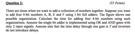
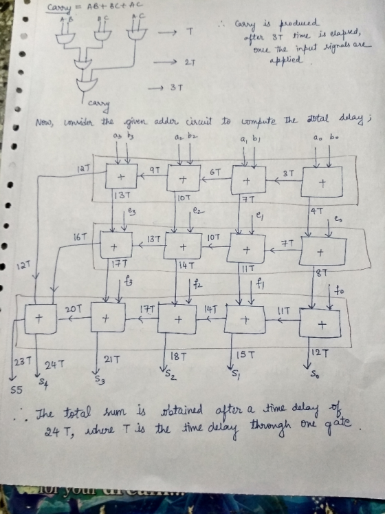
Question 2: (35 Points) There are times when we want to add a collection of numbers...
For number 2 you can use exclusive-OR gates, but do not use multiplexers. 1. Design a...
 For number 2 you can use
exclusive-OR gates, but do not use multiplexers.
1. Design a 4-bit adder/subtractor using only full adders and EXCLUSIVE- OR gates. Do not use any multiplexers. 2. Design a combinational circuit using a minimum number of Full adders, and logic gates which will perform A plus B or minus B (A and B are signed numbers), depending on a mode select input, M. If M=0, addition is carried out; if M1, subtraction is carried out....
For number 2 you can use
exclusive-OR gates, but do not use multiplexers.
1. Design a 4-bit adder/subtractor using only full adders and EXCLUSIVE- OR gates. Do not use any multiplexers. 2. Design a combinational circuit using a minimum number of Full adders, and logic gates which will perform A plus B or minus B (A and B are signed numbers), depending on a mode select input, M. If M=0, addition is carried out; if M1, subtraction is carried out....
PROBLEM STATEMENT The mini-calculator will use a small ALU to perform arithmetic operations on two 4-bit values which are set using switches. The ALU operations described below are implemented with a...
 PROBLEM STATEMENT The mini-calculator will use a small ALU to perform arithmetic operations on two 4-bit values which are set using switches. The ALU operations described below are implemented with an Adder/Subtractor component. A pushbutton input allows the current arithmetic result to be saved. An upgraded mini-calculator allows the saved value to be used in place of B as one of the operands. The small ALU that you will design will use the 4-bit adder myadder4 to do several possible...
[Paperl (10 pts.) Design a circuit that takes in four 4-bit unsigned numbers, A (A3..Ao), B (B3.....
 [Paperl (10 pts.) Design a circuit that takes in four 4-bit unsigned numbers, A (A3..Ao), B (B3..Bo), C (C3-C), and D (D3..Do) and produces the 6-bit unsigned sum of those numbers. You should use three 4-bit adder blocks (74LS283's), and a minimal number of full adders or half adder build blocks. You should organize your adder circuits to perform as many additions in parallel (at the same time) as possible. Getting started: Write out the columns of addition and see...
2. Consider two adders: a 64-bit ripple-carry adder and a 64-bit carry-lookahead adder with 4-bit blocks....
 2. Consider two adders: a 64-bit ripple-carry adder and a 64-bit carry-lookahead adder with 4-bit blocks. These adders are built using only two-input gates. Each two-input gate has an area of 15 um', has a 50 ps delay, and has 20 ff of total gate capacitance. You may assume that the static power is negligible. (a) Determine the area, delay, and power of the adders (operating at 100 MHz and 1.2 V). (b) Draw a table containing the area, delay...
3. Digital circuits question. The figure below shows a 16-b carry-skip adder. It is composed of...
 3. Digital circuits question.
The figure below shows a 16-b carry-skip adder. It is composed of 4 4-bit ripple carry adders and some extra logic to route the carry. Each 4bit ripple carry adder generates a group propagate signal. This is used to determine when the carry-in is going to be propagated all the way to the carry-out. When this is the case, addition is sped up by allowing the carry-in to skip the block and become the carry-in of...
3. Digital circuits question.
The figure below shows a 16-b carry-skip adder. It is composed of 4 4-bit ripple carry adders and some extra logic to route the carry. Each 4bit ripple carry adder generates a group propagate signal. This is used to determine when the carry-in is going to be propagated all the way to the carry-out. When this is the case, addition is sped up by allowing the carry-in to skip the block and become the carry-in of...
number 4 and 5 please! PROBLEM STATEMENT A logic circuit is needed to add multi-bit binary...
 number 4 and 5 please!
PROBLEM STATEMENT A logic circuit is needed to add multi-bit binary numbers. A 2-level circuit that would add two four-bit numbers would have 9 inputs and five outputs. Although a 2-level SOP or POS circuit theoretically would be very fast, it has numerous drawbacks that make it impractical. The design would be very complex in terms of the number of logic gates. The number of inputs for each gate would challenge target technologies. Testing would...
number 4 and 5 please!
PROBLEM STATEMENT A logic circuit is needed to add multi-bit binary numbers. A 2-level circuit that would add two four-bit numbers would have 9 inputs and five outputs. Although a 2-level SOP or POS circuit theoretically would be very fast, it has numerous drawbacks that make it impractical. The design would be very complex in terms of the number of logic gates. The number of inputs for each gate would challenge target technologies. Testing would...
(Don't do the simulation If you don't have LigoSim to simulate) I appreciate your efforts and...
(Don't do the simulation If you don't have LigoSim to simulate) I appreciate your efforts and time in advance! a)Simulate and test a 1-bit full adder. Use 2-input exclusive OR gates to realize Sum. Use an SOP form to realize Cout b) Simulate and test a 4-bit adder circuit using serially interconnected 1-bit full adder sub-circuits. The adder will be able to add 4 bit positive numbers and should be able to add 15 and 15 to get 30. c)...
Question 7[ 20 Marks ] 1. The number of full and half-adders required to add 16-bit...
 Question 7[ 20 Marks ] 1. The number of full and half-adders required to add 16-bit numbers is A. 8 half-adders, 8 full-adders B. 1 half-adder, 15 full-adders C. 16 half-adders, 0 full-adders D. 4 half-adders, 12 full-adders 2. How much of the following are needed to make 4 * 16 decoder 2. How much of the following are needed to make 4 * 16 decoder A. one 1*2 and two 3*8 decoders B. two 1*2 and two 3*8 decoders...
Please; I need an answer only for part C; thanks a) Simulate and test a 1-bit...
Please; I need an answer only for part C; thanks a) Simulate and test a 1-bit full adder. Use 2-input exclusive OR gates to realize Sum. Use an SOP form to realize Cout (see the back page of this handout). Save the circuit. Save the schematic by using File|Export. b) Simulate and test a 4-bit adder circuit using serially interconnected 1-bit full adder sub-circuits. The adder will be able to add 4 bit positive numbers and should be able to...
Question: Part 1: In the second part of this lab, we will extend our adder to...
 Question:
Part 1:
In the second part of this lab, we will extend our adder to also allow for subtraction of the second number from the first. To implement this, we must take the 2's compliment of the second number and add it to the first. This can be implemented using the circuit shown in Section 4.4.2 of the notes, which is shown again here in Figure 2. B3 A3 B2 A B, A, B, A, -SM 0: Add 1:...
Question:
Part 1:
In the second part of this lab, we will extend our adder to also allow for subtraction of the second number from the first. To implement this, we must take the 2's compliment of the second number and add it to the first. This can be implemented using the circuit shown in Section 4.4.2 of the notes, which is shown again here in Figure 2. B3 A3 B2 A B, A, B, A, -SM 0: Add 1:...
 For number 2 you can use
exclusive-OR gates, but do not use multiplexers.
1. Design a 4-bit adder/subtractor using only full adders and EXCLUSIVE- OR gates. Do not use any multiplexers. 2. Design a combinational circuit using a minimum number of Full adders, and logic gates which will perform A plus B or minus B (A and B are signed numbers), depending on a mode select input, M. If M=0, addition is carried out; if M1, subtraction is carried out....
For number 2 you can use
exclusive-OR gates, but do not use multiplexers.
1. Design a 4-bit adder/subtractor using only full adders and EXCLUSIVE- OR gates. Do not use any multiplexers. 2. Design a combinational circuit using a minimum number of Full adders, and logic gates which will perform A plus B or minus B (A and B are signed numbers), depending on a mode select input, M. If M=0, addition is carried out; if M1, subtraction is carried out....
 PROBLEM STATEMENT The mini-calculator will use a small ALU to perform arithmetic operations on two 4-bit values which are set using switches. The ALU operations described below are implemented with an Adder/Subtractor component. A pushbutton input allows the current arithmetic result to be saved. An upgraded mini-calculator allows the saved value to be used in place of B as one of the operands. The small ALU that you will design will use the 4-bit adder myadder4 to do several possible...
 [Paperl (10 pts.) Design a circuit that takes in four 4-bit unsigned numbers, A (A3..Ao), B (B3..Bo), C (C3-C), and D (D3..Do) and produces the 6-bit unsigned sum of those numbers. You should use three 4-bit adder blocks (74LS283's), and a minimal number of full adders or half adder build blocks. You should organize your adder circuits to perform as many additions in parallel (at the same time) as possible. Getting started: Write out the columns of addition and see...
 2. Consider two adders: a 64-bit ripple-carry adder and a 64-bit carry-lookahead adder with 4-bit blocks. These adders are built using only two-input gates. Each two-input gate has an area of 15 um', has a 50 ps delay, and has 20 ff of total gate capacitance. You may assume that the static power is negligible. (a) Determine the area, delay, and power of the adders (operating at 100 MHz and 1.2 V). (b) Draw a table containing the area, delay...
 3. Digital circuits question.
The figure below shows a 16-b carry-skip adder. It is composed of 4 4-bit ripple carry adders and some extra logic to route the carry. Each 4bit ripple carry adder generates a group propagate signal. This is used to determine when the carry-in is going to be propagated all the way to the carry-out. When this is the case, addition is sped up by allowing the carry-in to skip the block and become the carry-in of...
3. Digital circuits question.
The figure below shows a 16-b carry-skip adder. It is composed of 4 4-bit ripple carry adders and some extra logic to route the carry. Each 4bit ripple carry adder generates a group propagate signal. This is used to determine when the carry-in is going to be propagated all the way to the carry-out. When this is the case, addition is sped up by allowing the carry-in to skip the block and become the carry-in of...
 number 4 and 5 please!
PROBLEM STATEMENT A logic circuit is needed to add multi-bit binary numbers. A 2-level circuit that would add two four-bit numbers would have 9 inputs and five outputs. Although a 2-level SOP or POS circuit theoretically would be very fast, it has numerous drawbacks that make it impractical. The design would be very complex in terms of the number of logic gates. The number of inputs for each gate would challenge target technologies. Testing would...
number 4 and 5 please!
PROBLEM STATEMENT A logic circuit is needed to add multi-bit binary numbers. A 2-level circuit that would add two four-bit numbers would have 9 inputs and five outputs. Although a 2-level SOP or POS circuit theoretically would be very fast, it has numerous drawbacks that make it impractical. The design would be very complex in terms of the number of logic gates. The number of inputs for each gate would challenge target technologies. Testing would...
 Question 7[ 20 Marks ] 1. The number of full and half-adders required to add 16-bit numbers is A. 8 half-adders, 8 full-adders B. 1 half-adder, 15 full-adders C. 16 half-adders, 0 full-adders D. 4 half-adders, 12 full-adders 2. How much of the following are needed to make 4 * 16 decoder 2. How much of the following are needed to make 4 * 16 decoder A. one 1*2 and two 3*8 decoders B. two 1*2 and two 3*8 decoders...
 Question:
Part 1:
In the second part of this lab, we will extend our adder to also allow for subtraction of the second number from the first. To implement this, we must take the 2's compliment of the second number and add it to the first. This can be implemented using the circuit shown in Section 4.4.2 of the notes, which is shown again here in Figure 2. B3 A3 B2 A B, A, B, A, -SM 0: Add 1:...
Question:
Part 1:
In the second part of this lab, we will extend our adder to also allow for subtraction of the second number from the first. To implement this, we must take the 2's compliment of the second number and add it to the first. This can be implemented using the circuit shown in Section 4.4.2 of the notes, which is shown again here in Figure 2. B3 A3 B2 A B, A, B, A, -SM 0: Add 1:...
Most questions answered within 3 hours.
-
Where is the error in this code sequence?
String s1 = "Hello";
String s2 = "ello";...
asked 10 months ago -
Financial data for Joel de Paris, Inc., for last year
follow:
Joel de Paris, Inc.
Balance...
asked 10 months ago -
Consider this reaction:
Al2(SO4)3 (aq)+ BaCl3
(aq) Al2Cl6 (aq)- +
3BaSO4(s) . What is the...
asked 10 months ago -
Suppose that Savneet is considering increasing her
recent random sample from 20 car rentals to 40...
asked 10 months ago -
Trucks arrive at an unloading terminal at an average rate of 120
per hour.
Trucks arrive...
asked 10 months ago -
Why are methanol and ethanol completely soluble in water while
octanol is not very little soluble....
asked 10 months ago -
A facilities manager at a university reads in a research report
that the mean amount of...
asked 10 months ago -
When the CuSO4 is rehydrated by adding water to the anhydrous
compound, is this an endothermic...
asked 10 months ago -
A ray of sunlight is passing from diamond into crown glass; the
angle of incidence is...
asked 10 months ago -
A block of mass 0.249 kg is placed on top of a light, vertical
spring of...
asked 10 months ago -
how do the kidneys compensate in the presences of acidosis
a) trigger hyperventilate
b) reserve acid...
asked 10 months ago -
Question 501 pts
The rental rate of capital to the firm increases. Which of the
following...
asked 10 months ago