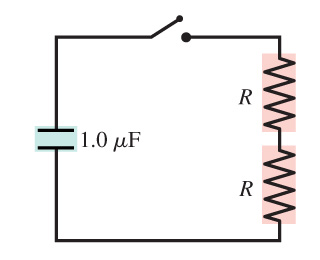
| Consider the circuit shown in (Figure 1). Suppose that R = 3.0
kΩ .
You may want to review (Pages 743 - 745) . Figure1 of 1The circuit is shown in the figure. A 1.0- microfarad capacitor, an opened switch, and two resistors of the same resistances R are connected in series.
|
Part A What is the time constant for the discharge of the capacitor? |
Homework Answers

Add Answer to:
Consider the circuit shown in (Figure 1). Suppose that R = 3.0
kΩ .
You may...
Draw a circuit diagram for the circuit of (Figure 1). You may want to review (Page...
 Draw a circuit diagram for the circuit of (Figure 1).
You may want to review (Page 728) .
Figure
1 of 1A circuit is shown in the figure. A 12-volt battery is
connected by wires to two resistors and a capacitor. The positive
terminal of the battery is connected to a 50-ohm resistor, and the
negative terminal of the battery is connected to one terminal of a
10-microfarad capacitor. Two wires are connected to the other
terminal of a 50-ohm...
Draw a circuit diagram for the circuit of (Figure 1).
You may want to review (Page 728) .
Figure
1 of 1A circuit is shown in the figure. A 12-volt battery is
connected by wires to two resistors and a capacitor. The positive
terminal of the battery is connected to a 50-ohm resistor, and the
negative terminal of the battery is connected to one terminal of a
10-microfarad capacitor. Two wires are connected to the other
terminal of a 50-ohm...
Consider the circuit shown in the figure(Figure 1). Suppose the four resistors in this circuit have...
 Consider the circuit shown in the figure(Figure 1). Suppose the four resistors in this circuit have the values R1 = 12 12, R2 = 7.0 N, R3 = 7.9 2 , and R4 = 12 12, and that the emf of the battery is € = 18 V You may want to review (Pages 748 - 751) Part A Find the current through each resistor using the rules for series and parallel resistors. Express vour answers using two significant figures...
Consider the circuit shown in (Figure 1) . Suppose that R = 6.0 k? . What...
 Consider the circuit shown in (Figure 1) . Suppose that R = 6.0
k? . What is the time constant for the discharge of the
capacitor?
Consider the circuit shown in (Figure 1) . Suppose that R = 6.0
k? . What is the time constant for the discharge of the
capacitor?
Consider the circuit shown in (Figure 1) . Suppose thatR = 2.0k? . What is the...
 Consider the circuit shown in (Figure 1) . Suppose
thatR = 2.0k? .
What is the time constant for the discharge of the
capacitor?
And with this image, what is the time constant for the discharge
of the capacitor?
Consider the circuit shown in (Figure 1) . Suppose thatR = 2.0k? . What is the time constant for the discharge of the capacitor? And with this image, what is the time constant for the discharge of the capacitor?
Consider the circuit shown in (Figure 1) . Suppose
thatR = 2.0k? .
What is the time constant for the discharge of the
capacitor?
And with this image, what is the time constant for the discharge
of the capacitor?
Consider the circuit shown in (Figure 1) . Suppose thatR = 2.0k? . What is the time constant for the discharge of the capacitor? And with this image, what is the time constant for the discharge of the capacitor?
ul Review Constants Consider the circuit shown in (Figure 1). Suppose that C = 16.0 nF,...
 ul Review Constants Consider the circuit shown in (Figure 1). Suppose that C = 16.0 nF, L = 26.0 mH, and R = 70.0 12. Part A For related problemsolving tips and strategies, you may want to view a Video Tutor Solution of An underdamped l- P-C series circuit. Calculate the oscillation frequency of the circuit once the capacitor has been charged and the switch has been connected to point a. Express your answer in hertz. I ALO ROO? 1...
Consider the circuit shown in (Figure 1) , where all resistors have the same resistance R....
 Consider the circuit shown in
(Figure
1)
, where all resistors have the same resistance R.
At
t=0,
with the capacitor C
uncharged, the switch is closed.At
t=0,
the three currents can be determined by analyzing a simpler, but
equivalent, circuit. Identify this simpler circuit and use it to
find the values of
I1
,
I2,
and
I3
at
t=0.
Consider the circuit shown in (Figure 1) , where all resistors have the same resistance R. At t=0, with the...
Consider the circuit shown in
(Figure
1)
, where all resistors have the same resistance R.
At
t=0,
with the capacitor C
uncharged, the switch is closed.At
t=0,
the three currents can be determined by analyzing a simpler, but
equivalent, circuit. Identify this simpler circuit and use it to
find the values of
I1
,
I2,
and
I3
at
t=0.
Consider the circuit shown in (Figure 1) , where all resistors have the same resistance R. At t=0, with the...
Consider a series RC circuit as in the figure below for which R = 7.00 M12,...
 Consider a series RC circuit as in the figure below for which R = 7.00 M12, C = 4.00 uF, and ε = 35.0 V. c: R + E (a) Find the time constant of the circuit. S (b) What is the maximum charge on the capacitor after the switch is thrown closed? μα (c) Find the current in the resistor 10.0 s after the switch is closed. РА
Consider the circuit shown in (Figure 1). Suppose that R = 6 kΩ. Find the current...
 Consider the circuit shown in (Figure 1). Suppose that R = 6
kΩ.
Find the current io in the circuit by making a succession of
appropriate source transformations.
Express your answer to three significant figures and include the
appropriate units.
Work back through the circuit to find the magnitude of the power
developed by the 120 V source.
Express your answer to three significant figures and include the
appropriate units.
40 kΩ Αν 4 kΩ 2.5 kΩ Αν +) 120...
Consider the circuit shown in (Figure 1). Suppose that R = 6
kΩ.
Find the current io in the circuit by making a succession of
appropriate source transformations.
Express your answer to three significant figures and include the
appropriate units.
Work back through the circuit to find the magnitude of the power
developed by the 120 V source.
Express your answer to three significant figures and include the
appropriate units.
40 kΩ Αν 4 kΩ 2.5 kΩ Αν +) 120...
Consider a series RC circuit as in the figure below for which R = 8.00 M2,...
 Consider a series RC circuit as in the figure below for which R = 8.00 M2, C = 4.00 uF, and ε = 34.0 V. sa (a) Find the time constant of the circuit. (b) What is the maximum charge on the capacitor after the switch is thrown closed? UC (c) Find the current in the resistor 10.0 s after the switch is closed. НА
The circuit in the figure below contains two resistors, R1-1.8 kΩ and R2 2.8 k. and...
 The circuit in the figure below contains two resistors, R1-1.8 kΩ and R2 2.8 k. and two capacitors, C1-1.7 μF and C3 = 2.5 μF, connected to a battery with emf ε-105 v. If there are no charges on the capacitors before switch s is closed, determine the charges q1 and q2 on capacitors C1 and C2, respectively, as functions of time, after the switch is closed. Hint: First reconstruct the circuit so that it becomes a simple RC circuit...
 Draw a circuit diagram for the circuit of (Figure 1).
You may want to review (Page 728) .
Figure
1 of 1A circuit is shown in the figure. A 12-volt battery is
connected by wires to two resistors and a capacitor. The positive
terminal of the battery is connected to a 50-ohm resistor, and the
negative terminal of the battery is connected to one terminal of a
10-microfarad capacitor. Two wires are connected to the other
terminal of a 50-ohm...
Draw a circuit diagram for the circuit of (Figure 1).
You may want to review (Page 728) .
Figure
1 of 1A circuit is shown in the figure. A 12-volt battery is
connected by wires to two resistors and a capacitor. The positive
terminal of the battery is connected to a 50-ohm resistor, and the
negative terminal of the battery is connected to one terminal of a
10-microfarad capacitor. Two wires are connected to the other
terminal of a 50-ohm...
 Consider the circuit shown in the figure(Figure 1). Suppose the four resistors in this circuit have the values R1 = 12 12, R2 = 7.0 N, R3 = 7.9 2 , and R4 = 12 12, and that the emf of the battery is € = 18 V You may want to review (Pages 748 - 751) Part A Find the current through each resistor using the rules for series and parallel resistors. Express vour answers using two significant figures...
 Consider the circuit shown in (Figure 1) . Suppose that R = 6.0
k? . What is the time constant for the discharge of the
capacitor?
Consider the circuit shown in (Figure 1) . Suppose that R = 6.0
k? . What is the time constant for the discharge of the
capacitor?
 Consider the circuit shown in (Figure 1) . Suppose
thatR = 2.0k? .
What is the time constant for the discharge of the
capacitor?
And with this image, what is the time constant for the discharge
of the capacitor?
Consider the circuit shown in (Figure 1) . Suppose thatR = 2.0k? . What is the time constant for the discharge of the capacitor? And with this image, what is the time constant for the discharge of the capacitor?
Consider the circuit shown in (Figure 1) . Suppose
thatR = 2.0k? .
What is the time constant for the discharge of the
capacitor?
And with this image, what is the time constant for the discharge
of the capacitor?
Consider the circuit shown in (Figure 1) . Suppose thatR = 2.0k? . What is the time constant for the discharge of the capacitor? And with this image, what is the time constant for the discharge of the capacitor?
 ul Review Constants Consider the circuit shown in (Figure 1). Suppose that C = 16.0 nF, L = 26.0 mH, and R = 70.0 12. Part A For related problemsolving tips and strategies, you may want to view a Video Tutor Solution of An underdamped l- P-C series circuit. Calculate the oscillation frequency of the circuit once the capacitor has been charged and the switch has been connected to point a. Express your answer in hertz. I ALO ROO? 1...
 Consider the circuit shown in
(Figure
1)
, where all resistors have the same resistance R.
At
t=0,
with the capacitor C
uncharged, the switch is closed.At
t=0,
the three currents can be determined by analyzing a simpler, but
equivalent, circuit. Identify this simpler circuit and use it to
find the values of
I1
,
I2,
and
I3
at
t=0.
Consider the circuit shown in (Figure 1) , where all resistors have the same resistance R. At t=0, with the...
Consider the circuit shown in
(Figure
1)
, where all resistors have the same resistance R.
At
t=0,
with the capacitor C
uncharged, the switch is closed.At
t=0,
the three currents can be determined by analyzing a simpler, but
equivalent, circuit. Identify this simpler circuit and use it to
find the values of
I1
,
I2,
and
I3
at
t=0.
Consider the circuit shown in (Figure 1) , where all resistors have the same resistance R. At t=0, with the...
 Consider a series RC circuit as in the figure below for which R = 7.00 M12, C = 4.00 uF, and ε = 35.0 V. c: R + E (a) Find the time constant of the circuit. S (b) What is the maximum charge on the capacitor after the switch is thrown closed? μα (c) Find the current in the resistor 10.0 s after the switch is closed. РА
 Consider the circuit shown in (Figure 1). Suppose that R = 6
kΩ.
Find the current io in the circuit by making a succession of
appropriate source transformations.
Express your answer to three significant figures and include the
appropriate units.
Work back through the circuit to find the magnitude of the power
developed by the 120 V source.
Express your answer to three significant figures and include the
appropriate units.
40 kΩ Αν 4 kΩ 2.5 kΩ Αν +) 120...
Consider the circuit shown in (Figure 1). Suppose that R = 6
kΩ.
Find the current io in the circuit by making a succession of
appropriate source transformations.
Express your answer to three significant figures and include the
appropriate units.
Work back through the circuit to find the magnitude of the power
developed by the 120 V source.
Express your answer to three significant figures and include the
appropriate units.
40 kΩ Αν 4 kΩ 2.5 kΩ Αν +) 120...
 Consider a series RC circuit as in the figure below for which R = 8.00 M2, C = 4.00 uF, and ε = 34.0 V. sa (a) Find the time constant of the circuit. (b) What is the maximum charge on the capacitor after the switch is thrown closed? UC (c) Find the current in the resistor 10.0 s after the switch is closed. НА
 The circuit in the figure below contains two resistors, R1-1.8 kΩ and R2 2.8 k. and two capacitors, C1-1.7 μF and C3 = 2.5 μF, connected to a battery with emf ε-105 v. If there are no charges on the capacitors before switch s is closed, determine the charges q1 and q2 on capacitors C1 and C2, respectively, as functions of time, after the switch is closed. Hint: First reconstruct the circuit so that it becomes a simple RC circuit...
Most questions answered within 3 hours.
-
Where is the error in this code sequence?
String s1 = "Hello";
String s2 = "ello";...
asked 10 months ago -
Financial data for Joel de Paris, Inc., for last year
follow:
Joel de Paris, Inc.
Balance...
asked 10 months ago -
Consider this reaction:
Al2(SO4)3 (aq)+ BaCl3
(aq) Al2Cl6 (aq)- +
3BaSO4(s) . What is the...
asked 10 months ago -
Suppose that Savneet is considering increasing her
recent random sample from 20 car rentals to 40...
asked 10 months ago -
Trucks arrive at an unloading terminal at an average rate of 120
per hour.
Trucks arrive...
asked 10 months ago -
Why are methanol and ethanol completely soluble in water while
octanol is not very little soluble....
asked 10 months ago -
A facilities manager at a university reads in a research report
that the mean amount of...
asked 10 months ago -
When the CuSO4 is rehydrated by adding water to the anhydrous
compound, is this an endothermic...
asked 10 months ago -
A ray of sunlight is passing from diamond into crown glass; the
angle of incidence is...
asked 10 months ago -
A block of mass 0.249 kg is placed on top of a light, vertical
spring of...
asked 10 months ago -
how do the kidneys compensate in the presences of acidosis
a) trigger hyperventilate
b) reserve acid...
asked 10 months ago -
Question 501 pts
The rental rate of capital to the firm increases. Which of the
following...
asked 10 months ago