
Homework Answers
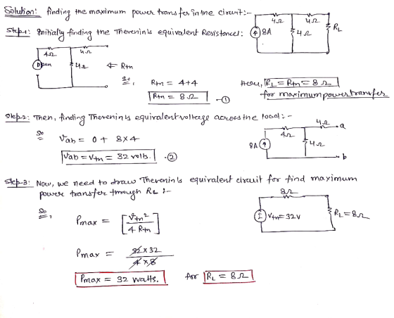
The answer is an option (8) 32 watts.
Explanation:
Add Answer to:
Question 3 Find the maximum power transferred (in W) to the load resistor, R1, in the...
Maximum Power Transfer Learning Goal: To find the load resistance and load power for the maximum...
 Maximum Power Transfer
Learning Goal:
To find the load resistance and load power for the maximum power
transferred to a load.
A resistive network containing independent and dependent sources
can be modeled with a Thévenin equivalent circuit, as shown below.
Maximum power transfer occurs when the load resistance
RLequals the Thévenin resistance RTh
Part A
Find the Thévenin equivalent circuit with respect to the
terminals a,b for the circuit above. What is the
Thévenin voltage VTh?
Express your answer in...
Maximum Power Transfer
Learning Goal:
To find the load resistance and load power for the maximum power
transferred to a load.
A resistive network containing independent and dependent sources
can be modeled with a Thévenin equivalent circuit, as shown below.
Maximum power transfer occurs when the load resistance
RLequals the Thévenin resistance RTh
Part A
Find the Thévenin equivalent circuit with respect to the
terminals a,b for the circuit above. What is the
Thévenin voltage VTh?
Express your answer in...
1- What is the power dissipated by the load resistor R1 in each of the three...
 1- What is the power dissipated by the load resistor R1 in each
of the three circuits ?
2- What is the maximum current through the diodes in each of the
three circuits ?
Capacitor value 220uF
11 4V 60Hz - 1.5k 3 R1 I c1 T Circuit 2
1- What is the power dissipated by the load resistor R1 in each
of the three circuits ?
2- What is the maximum current through the diodes in each of the
three circuits ?
Capacitor value 220uF
11 4V 60Hz - 1.5k 3 R1 I c1 T Circuit 2
2. Norton Circuit and Maximum Power For the circuit shown calculate the maximum power transfer in...
 2. Norton Circuit and Maximum Power For the circuit shown calculate the maximum power transfer in [W] that can be achieved to a proper load resistor connected at the nodes a and b. Use Norton equivalent circuit concept in your analysis. a 24 3 A 12 0 48 V b
Find the maximum power transferred to resistor R in the circuit below. 22 kΩ 100V(±) 40...
 Find the maximum power transferred to resistor R in the circuit below. 22 kΩ 100V(±) 40 kΩ 30 kΩ ら
MULTISIM 10.65 The variable load resistor R¡ in the circuit shown in PSPICE Fig. P10.65 is...
 MULTISIM 10.65 The variable load resistor R¡ in the circuit shown in PSPICE Fig. P10.65 is adjusted for maximum average power transfer to RL a) Find the maximum average power. b) What percentage of the average power devel- oped by the ideal voltage source is delivered to Rź when R is absorbing maximum average power? c) Test your solution by showing that the power developed by the ideal voltage source equals the power dissipated in the circuit. Figure P10.65 1212...
please solve number 3 only #2 Find the maximum power transfer to resistor R in the...
 please solve number 3 only
#2 Find the maximum power transfer to resistor R in the following circuit (hints: Remove R first, & do Thevenin's equivalent to calculate R; then find Power) (pts. 20) 5 Ω 10 Ω 50 Ω 6 Ω ΕΛ V, 3. Find the w of following opamp circuit (pts. 20) 80 ΚΩ 80 ΚΩ 5 ΚΩ 40 ΚΩ + 1ο 0.3V 20 ΚΩ 0.7V
please solve number 3 only
#2 Find the maximum power transfer to resistor R in the following circuit (hints: Remove R first, & do Thevenin's equivalent to calculate R; then find Power) (pts. 20) 5 Ω 10 Ω 50 Ω 6 Ω ΕΛ V, 3. Find the w of following opamp circuit (pts. 20) 80 ΚΩ 80 ΚΩ 5 ΚΩ 40 ΚΩ + 1ο 0.3V 20 ΚΩ 0.7V
In the circuit below, find the maximum power that this circuit can deliver to a load...
 In the circuit below, find the maximum power that this circuit can deliver to a load if the load can take any complex impedance. H 1022 -j812 20 4 200 V Voc Ol. 5w O II. 10 W O III. 20 W IV.2.5 W
Q#2 The variable resistor Ro in the circuit below is adjusted for maximum power transfer to...
 Q#2 The variable resistor Ro in the circuit below is adjusted for maximum power transfer to Ro a) b) c) Find the value of Ro Find the maximum power that can be delivered to Ro What percentage of the total power developed in the circuit is delivered to Ro found in parta)? 316is 16? 32 ? A 180 ? 200 V 64 ? 48 ?
Given: The circuit shown above. Required: Calculate the value of the load resistor, RL, that will...
 Given: The circuit shown above.
Required: Calculate the value of the load resistor,
RL, that will draw the maximum power from the circuit.
Also, calculate the maximum amount of power that can be delivered
to RL from the circuit.
Solution:
RL = ______ Ω
Pmx = ______ W
15 о 12 O
Given: The circuit shown above.
Required: Calculate the value of the load resistor,
RL, that will draw the maximum power from the circuit.
Also, calculate the maximum amount of power that can be delivered
to RL from the circuit.
Solution:
RL = ______ Ω
Pmx = ______ W
15 о 12 O
***Four*** Question 13 (1 point) To ensure maximum power to the load, the maximum power transfer...
 ***Four***
Question 13 (1 point)
To ensure maximum power to the load, the maximum power transfer
theorem is used to determine which of the following for the
load?
Question 13 options:
A)
Resistance
B)
Voltage
C)
Impedance
D)
Current
Question 14 (1 point)
Because the reactances of a circuit are frequently dependent,
the Thevenin circuit that is found for a particular network is
applicable at any frequency.
Question 14 options:
True
False
Question 15 (1 point)
An application of the...
***Four***
Question 13 (1 point)
To ensure maximum power to the load, the maximum power transfer
theorem is used to determine which of the following for the
load?
Question 13 options:
A)
Resistance
B)
Voltage
C)
Impedance
D)
Current
Question 14 (1 point)
Because the reactances of a circuit are frequently dependent,
the Thevenin circuit that is found for a particular network is
applicable at any frequency.
Question 14 options:
True
False
Question 15 (1 point)
An application of the...
 Maximum Power Transfer
Learning Goal:
To find the load resistance and load power for the maximum power
transferred to a load.
A resistive network containing independent and dependent sources
can be modeled with a Thévenin equivalent circuit, as shown below.
Maximum power transfer occurs when the load resistance
RLequals the Thévenin resistance RTh
Part A
Find the Thévenin equivalent circuit with respect to the
terminals a,b for the circuit above. What is the
Thévenin voltage VTh?
Express your answer in...
Maximum Power Transfer
Learning Goal:
To find the load resistance and load power for the maximum power
transferred to a load.
A resistive network containing independent and dependent sources
can be modeled with a Thévenin equivalent circuit, as shown below.
Maximum power transfer occurs when the load resistance
RLequals the Thévenin resistance RTh
Part A
Find the Thévenin equivalent circuit with respect to the
terminals a,b for the circuit above. What is the
Thévenin voltage VTh?
Express your answer in...
 1- What is the power dissipated by the load resistor R1 in each
of the three circuits ?
2- What is the maximum current through the diodes in each of the
three circuits ?
Capacitor value 220uF
11 4V 60Hz - 1.5k 3 R1 I c1 T Circuit 2
1- What is the power dissipated by the load resistor R1 in each
of the three circuits ?
2- What is the maximum current through the diodes in each of the
three circuits ?
Capacitor value 220uF
11 4V 60Hz - 1.5k 3 R1 I c1 T Circuit 2
 2. Norton Circuit and Maximum Power For the circuit shown calculate the maximum power transfer in [W] that can be achieved to a proper load resistor connected at the nodes a and b. Use Norton equivalent circuit concept in your analysis. a 24 3 A 12 0 48 V b
 Find the maximum power transferred to resistor R in the circuit below. 22 kΩ 100V(±) 40 kΩ 30 kΩ ら
 MULTISIM 10.65 The variable load resistor R¡ in the circuit shown in PSPICE Fig. P10.65 is adjusted for maximum average power transfer to RL a) Find the maximum average power. b) What percentage of the average power devel- oped by the ideal voltage source is delivered to Rź when R is absorbing maximum average power? c) Test your solution by showing that the power developed by the ideal voltage source equals the power dissipated in the circuit. Figure P10.65 1212...
 please solve number 3 only
#2 Find the maximum power transfer to resistor R in the following circuit (hints: Remove R first, & do Thevenin's equivalent to calculate R; then find Power) (pts. 20) 5 Ω 10 Ω 50 Ω 6 Ω ΕΛ V, 3. Find the w of following opamp circuit (pts. 20) 80 ΚΩ 80 ΚΩ 5 ΚΩ 40 ΚΩ + 1ο 0.3V 20 ΚΩ 0.7V
please solve number 3 only
#2 Find the maximum power transfer to resistor R in the following circuit (hints: Remove R first, & do Thevenin's equivalent to calculate R; then find Power) (pts. 20) 5 Ω 10 Ω 50 Ω 6 Ω ΕΛ V, 3. Find the w of following opamp circuit (pts. 20) 80 ΚΩ 80 ΚΩ 5 ΚΩ 40 ΚΩ + 1ο 0.3V 20 ΚΩ 0.7V
 In the circuit below, find the maximum power that this circuit can deliver to a load if the load can take any complex impedance. H 1022 -j812 20 4 200 V Voc Ol. 5w O II. 10 W O III. 20 W IV.2.5 W
 Q#2 The variable resistor Ro in the circuit below is adjusted for maximum power transfer to Ro a) b) c) Find the value of Ro Find the maximum power that can be delivered to Ro What percentage of the total power developed in the circuit is delivered to Ro found in parta)? 316is 16? 32 ? A 180 ? 200 V 64 ? 48 ?
 Given: The circuit shown above.
Required: Calculate the value of the load resistor,
RL, that will draw the maximum power from the circuit.
Also, calculate the maximum amount of power that can be delivered
to RL from the circuit.
Solution:
RL = ______ Ω
Pmx = ______ W
15 о 12 O
Given: The circuit shown above.
Required: Calculate the value of the load resistor,
RL, that will draw the maximum power from the circuit.
Also, calculate the maximum amount of power that can be delivered
to RL from the circuit.
Solution:
RL = ______ Ω
Pmx = ______ W
15 о 12 O
 ***Four***
Question 13 (1 point)
To ensure maximum power to the load, the maximum power transfer
theorem is used to determine which of the following for the
load?
Question 13 options:
A)
Resistance
B)
Voltage
C)
Impedance
D)
Current
Question 14 (1 point)
Because the reactances of a circuit are frequently dependent,
the Thevenin circuit that is found for a particular network is
applicable at any frequency.
Question 14 options:
True
False
Question 15 (1 point)
An application of the...
***Four***
Question 13 (1 point)
To ensure maximum power to the load, the maximum power transfer
theorem is used to determine which of the following for the
load?
Question 13 options:
A)
Resistance
B)
Voltage
C)
Impedance
D)
Current
Question 14 (1 point)
Because the reactances of a circuit are frequently dependent,
the Thevenin circuit that is found for a particular network is
applicable at any frequency.
Question 14 options:
True
False
Question 15 (1 point)
An application of the...
Most questions answered within 3 hours.
-
Where is the error in this code sequence?
String s1 = "Hello";
String s2 = "ello";...
asked 10 months ago -
Financial data for Joel de Paris, Inc., for last year
follow:
Joel de Paris, Inc.
Balance...
asked 10 months ago -
Consider this reaction:
Al2(SO4)3 (aq)+ BaCl3
(aq) Al2Cl6 (aq)- +
3BaSO4(s) . What is the...
asked 10 months ago -
Suppose that Savneet is considering increasing her
recent random sample from 20 car rentals to 40...
asked 10 months ago -
Trucks arrive at an unloading terminal at an average rate of 120
per hour.
Trucks arrive...
asked 10 months ago -
Why are methanol and ethanol completely soluble in water while
octanol is not very little soluble....
asked 10 months ago -
A facilities manager at a university reads in a research report
that the mean amount of...
asked 10 months ago -
When the CuSO4 is rehydrated by adding water to the anhydrous
compound, is this an endothermic...
asked 10 months ago -
A ray of sunlight is passing from diamond into crown glass; the
angle of incidence is...
asked 10 months ago -
A block of mass 0.249 kg is placed on top of a light, vertical
spring of...
asked 10 months ago -
how do the kidneys compensate in the presences of acidosis
a) trigger hyperventilate
b) reserve acid...
asked 10 months ago -
Question 501 pts
The rental rate of capital to the firm increases. Which of the
following...
asked 10 months ago