
Homework Answers


Add Answer to:
Problemuǐ(30 points) Consider the circuit in Figure 1 1Ω 4A Figure I. DC resistive circuit Submit...
A) Given For the circuit: IK 1Ω 4A B) Determine 1) 2) 3) 4) 5) 6)...
 A) Given For the circuit: IK 1Ω 4A B) Determine 1) 2) 3) 4) 5) 6) 7) Sketch of the circuit with all currents information Sketch of the circuit with all voltages information. The power of the 2V independent voltage source. Indicate if it is active or passive element. The power of the 2ix dependent current source. Indicate if it is active or passive element. The power of the 1 Ω resistor. Indicate if it is active or passive element....
Problem 4a (15 points) For the transistor circuit shown in the figure, calculate the value of...
 Problem 4a (15 points) For the transistor circuit shown in the figure, calculate the value of the output voltage given β 49 and VBE-0.7V. Problem 4b (10 points) The charge entering an electric element (part) is shown in the figure. Find the current at t- 1.5 sec, t-2.5 sec and t 10 sec 30 0 246810 12 Problem 3 (25 points) For the circuit shown in the Figure, use the Mesh Analysis method, to find the value of the branch...
Name: Section: Jan. 31, 2018 1. Consider the circuit shown in figure 1 (a) Write the...
 Name: Section: Jan. 31, 2018 1. Consider the circuit shown in figure 1 (a) Write the mesh-current equations for the circuit. DO NOT SOLVE. (b) Write the node.voltage equations for the cireuit. DO NOT SOLVE 2. Consider the circuit shown in figure 2. The sinusoidal source is v,(04 sin (100t+90) volts (a) Transform the circuit to the frequency domain. (b) Use phasors with the mesh-current method to find the steady state expression for i(t). (c) Find the average power absorbed...
please solve them all 2) For the circuit shown in Figure 1. Find the following: A....
 please solve them all
2) For the circuit shown in Figure 1. Find the following: A. How many independent loops are present in the circuit? B. How many nodes are present in the circuit? C. Write a KVL equation at every independent loop (mesh) in the circuit in terms of the indicated voltage and current variables. D. Write a KCL equation at every node in the circuit. Write those equations using the indicated voltage variables by incorporating Ohm's Law for...
please solve them all
2) For the circuit shown in Figure 1. Find the following: A. How many independent loops are present in the circuit? B. How many nodes are present in the circuit? C. Write a KVL equation at every independent loop (mesh) in the circuit in terms of the indicated voltage and current variables. D. Write a KCL equation at every node in the circuit. Write those equations using the indicated voltage variables by incorporating Ohm's Law for...
PLEASE HELP! Jan. 31, 2018 Name: Section: I. Consider the circuit shown in figure (a) Write...
 PLEASE HELP!
Jan. 31, 2018 Name: Section: I. Consider the circuit shown in figure (a) Write the mesh-current equations (b) Write the for the circuit. D。~of SOL the circuit DO NOT SOLVE shown in figure 2. The sinusoidal source is the circuit to the frequency domain er the circuit (a) Transto with the mesh-current method to find thement (b) Use phasors with the mesh (c) Find the average power absorbed source is 、dt) = 2 sin (100t + 90") volts....
PLEASE HELP!
Jan. 31, 2018 Name: Section: I. Consider the circuit shown in figure (a) Write the mesh-current equations (b) Write the for the circuit. D。~of SOL the circuit DO NOT SOLVE shown in figure 2. The sinusoidal source is the circuit to the frequency domain er the circuit (a) Transto with the mesh-current method to find thement (b) Use phasors with the mesh (c) Find the average power absorbed source is 、dt) = 2 sin (100t + 90") volts....
Matlab question: Resistive networks are well-represented by linear equations. Consider the DC circuit shown below: Figure...
 Matlab question:
Resistive networks are well-represented by linear equations. Consider the DC circuit shown below: Figure 1 This problem can be converted into a system of simultaneous linear equations by applying Kirchhoff's law and Ohm's law. In circuit design, i represents current (measured in amperes, A), V represents voltage (in volts, V), and R represents resistance (in ohms, ohm). Kirchhoff's law states that the sum of the currents entering a node is equal to the sum of the currents leaving...
Matlab question:
Resistive networks are well-represented by linear equations. Consider the DC circuit shown below: Figure 1 This problem can be converted into a system of simultaneous linear equations by applying Kirchhoff's law and Ohm's law. In circuit design, i represents current (measured in amperes, A), V represents voltage (in volts, V), and R represents resistance (in ohms, ohm). Kirchhoff's law states that the sum of the currents entering a node is equal to the sum of the currents leaving...
Problem # 2 (20 pts) A) Given For the circuit . 20 B) Determine 1) Sketch...
 Problem # 2 (20 pts) A) Given For the circuit . 20 B) Determine 1) Sketch of the circuit with all currents information. 2) Sketch of the circuit with all voltages information. 3) The value of the voltage Vx. 4) The value of the resistance R. 5) The power at the 4A current source. Use only KVL, KCL and the Ohms Law. Eval uation Criteria Rubric for Reinforcement Problem # 3 Points Activities Step 1 Step 2 Step 3 Step...
Problem 4.32 Consider the circuit shown in (Figure 1). Use the mesh- current method to find...
 Problem 4.32 Consider the circuit shown in (Figure 1). Use the mesh- current method to find the branch currents ia - ze in the circuit. Take v1 = 32 V and ug = 2 V. Part A Find in Express your answer to three significant figures and include the appropriate units. HÅ ? Value Units Submit Previous Answers Request Answer X Incorrect; Try Again; 3 attempts remaining Part B Find is. Express your answer to three significant figures and include...
1. Why can the DSO only measure node voltages when the Function Generator is the power supply in ...
 1. Why can the DSO only measure node voltages when the Function Generator is the power supply in a circuit (unless it is using a current probe)? 2. Consider Figure 1. According to the calculations in the lab handout, if Z-1kΩ +/6914, then the phase difference (фи-фі) between u(t) and i (t) is 34.6". a. If this v(t) and i(t) were displayed on a DSO (v(t) being a node voltage and using a current probe for i(t) as shown in...
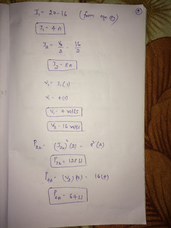
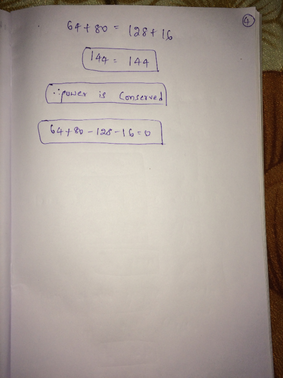
 A) Given For the circuit: IK 1Ω 4A B) Determine 1) 2) 3) 4) 5) 6) 7) Sketch of the circuit with all currents information Sketch of the circuit with all voltages information. The power of the 2V independent voltage source. Indicate if it is active or passive element. The power of the 2ix dependent current source. Indicate if it is active or passive element. The power of the 1 Ω resistor. Indicate if it is active or passive element....
 Problem 4a (15 points) For the transistor circuit shown in the figure, calculate the value of the output voltage given β 49 and VBE-0.7V. Problem 4b (10 points) The charge entering an electric element (part) is shown in the figure. Find the current at t- 1.5 sec, t-2.5 sec and t 10 sec 30 0 246810 12 Problem 3 (25 points) For the circuit shown in the Figure, use the Mesh Analysis method, to find the value of the branch...
 Name: Section: Jan. 31, 2018 1. Consider the circuit shown in figure 1 (a) Write the mesh-current equations for the circuit. DO NOT SOLVE. (b) Write the node.voltage equations for the cireuit. DO NOT SOLVE 2. Consider the circuit shown in figure 2. The sinusoidal source is v,(04 sin (100t+90) volts (a) Transform the circuit to the frequency domain. (b) Use phasors with the mesh-current method to find the steady state expression for i(t). (c) Find the average power absorbed...
 please solve them all
2) For the circuit shown in Figure 1. Find the following: A. How many independent loops are present in the circuit? B. How many nodes are present in the circuit? C. Write a KVL equation at every independent loop (mesh) in the circuit in terms of the indicated voltage and current variables. D. Write a KCL equation at every node in the circuit. Write those equations using the indicated voltage variables by incorporating Ohm's Law for...
please solve them all
2) For the circuit shown in Figure 1. Find the following: A. How many independent loops are present in the circuit? B. How many nodes are present in the circuit? C. Write a KVL equation at every independent loop (mesh) in the circuit in terms of the indicated voltage and current variables. D. Write a KCL equation at every node in the circuit. Write those equations using the indicated voltage variables by incorporating Ohm's Law for...
 PLEASE HELP!
Jan. 31, 2018 Name: Section: I. Consider the circuit shown in figure (a) Write the mesh-current equations (b) Write the for the circuit. D。~of SOL the circuit DO NOT SOLVE shown in figure 2. The sinusoidal source is the circuit to the frequency domain er the circuit (a) Transto with the mesh-current method to find thement (b) Use phasors with the mesh (c) Find the average power absorbed source is 、dt) = 2 sin (100t + 90") volts....
PLEASE HELP!
Jan. 31, 2018 Name: Section: I. Consider the circuit shown in figure (a) Write the mesh-current equations (b) Write the for the circuit. D。~of SOL the circuit DO NOT SOLVE shown in figure 2. The sinusoidal source is the circuit to the frequency domain er the circuit (a) Transto with the mesh-current method to find thement (b) Use phasors with the mesh (c) Find the average power absorbed source is 、dt) = 2 sin (100t + 90") volts....
 Matlab question:
Resistive networks are well-represented by linear equations. Consider the DC circuit shown below: Figure 1 This problem can be converted into a system of simultaneous linear equations by applying Kirchhoff's law and Ohm's law. In circuit design, i represents current (measured in amperes, A), V represents voltage (in volts, V), and R represents resistance (in ohms, ohm). Kirchhoff's law states that the sum of the currents entering a node is equal to the sum of the currents leaving...
Matlab question:
Resistive networks are well-represented by linear equations. Consider the DC circuit shown below: Figure 1 This problem can be converted into a system of simultaneous linear equations by applying Kirchhoff's law and Ohm's law. In circuit design, i represents current (measured in amperes, A), V represents voltage (in volts, V), and R represents resistance (in ohms, ohm). Kirchhoff's law states that the sum of the currents entering a node is equal to the sum of the currents leaving...
 Problem # 2 (20 pts) A) Given For the circuit . 20 B) Determine 1) Sketch of the circuit with all currents information. 2) Sketch of the circuit with all voltages information. 3) The value of the voltage Vx. 4) The value of the resistance R. 5) The power at the 4A current source. Use only KVL, KCL and the Ohms Law. Eval uation Criteria Rubric for Reinforcement Problem # 3 Points Activities Step 1 Step 2 Step 3 Step...
 Problem 4.32 Consider the circuit shown in (Figure 1). Use the mesh- current method to find the branch currents ia - ze in the circuit. Take v1 = 32 V and ug = 2 V. Part A Find in Express your answer to three significant figures and include the appropriate units. HÅ ? Value Units Submit Previous Answers Request Answer X Incorrect; Try Again; 3 attempts remaining Part B Find is. Express your answer to three significant figures and include...
 1. Why can the DSO only measure node voltages when the Function Generator is the power supply in a circuit (unless it is using a current probe)? 2. Consider Figure 1. According to the calculations in the lab handout, if Z-1kΩ +/6914, then the phase difference (фи-фі) between u(t) and i (t) is 34.6". a. If this v(t) and i(t) were displayed on a DSO (v(t) being a node voltage and using a current probe for i(t) as shown in...
Most questions answered within 3 hours.
-
Where is the error in this code sequence?
String s1 = "Hello";
String s2 = "ello";...
asked 10 months ago -
Financial data for Joel de Paris, Inc., for last year
follow:
Joel de Paris, Inc.
Balance...
asked 10 months ago -
Consider this reaction:
Al2(SO4)3 (aq)+ BaCl3
(aq) Al2Cl6 (aq)- +
3BaSO4(s) . What is the...
asked 10 months ago -
Suppose that Savneet is considering increasing her
recent random sample from 20 car rentals to 40...
asked 10 months ago -
Trucks arrive at an unloading terminal at an average rate of 120
per hour.
Trucks arrive...
asked 10 months ago -
Why are methanol and ethanol completely soluble in water while
octanol is not very little soluble....
asked 10 months ago -
A facilities manager at a university reads in a research report
that the mean amount of...
asked 10 months ago -
When the CuSO4 is rehydrated by adding water to the anhydrous
compound, is this an endothermic...
asked 10 months ago -
A ray of sunlight is passing from diamond into crown glass; the
angle of incidence is...
asked 10 months ago -
A block of mass 0.249 kg is placed on top of a light, vertical
spring of...
asked 10 months ago -
how do the kidneys compensate in the presences of acidosis
a) trigger hyperventilate
b) reserve acid...
asked 10 months ago -
Question 501 pts
The rental rate of capital to the firm increases. Which of the
following...
asked 10 months ago