
Homework Answers
Add Answer to:
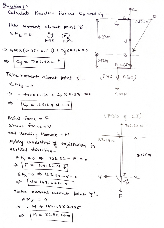
QUESTION 1 Given the dimension a = 176 mm and the applied load is 400 N,...
Determ ine the internal forces at point J for the structure shown, where member BD can...
 Determ ine the internal forces at point J for the structure shown, where member BD can only carry axial forces. Take the dimension a 176 mm and the external load P 500 M a mm 225 mm B 120 mm 225 mm A P NV 135 mm axial force: Number Units (tolerance 1 N, magnitude only) FJ shear force: SF= Number Units (tolerance 1 N, magnitude only) bending moment Number Units (tolerance 100 N mm, magnitude only) BMJ
Determ ine...
Determ ine the internal forces at point J for the structure shown, where member BD can only carry axial forces. Take the dimension a 176 mm and the external load P 500 M a mm 225 mm B 120 mm 225 mm A P NV 135 mm axial force: Number Units (tolerance 1 N, magnitude only) FJ shear force: SF= Number Units (tolerance 1 N, magnitude only) bending moment Number Units (tolerance 100 N mm, magnitude only) BMJ
Determ ine...
Q1. Load and Stress Analysis The countershaft with the reverse gears attached to is shown in figu...
 machine design question
Q1. Load and Stress Analysis The countershaft with the reverse gears attached to is shown in figure 2 with the dimension given in table 1. Gear A receives power from another gear with the transmitted force Fa applied at the pressure angle au as shown. The power is transmitted through the shaft and delivered through gear B through a transmitted force Fs at the pressure angle shown. You can find the values of the parameters in table...
machine design question
Q1. Load and Stress Analysis The countershaft with the reverse gears attached to is shown in figure 2 with the dimension given in table 1. Gear A receives power from another gear with the transmitted force Fa applied at the pressure angle au as shown. The power is transmitted through the shaft and delivered through gear B through a transmitted force Fs at the pressure angle shown. You can find the values of the parameters in table...
A simply supported prismatic beam is loaded with a load applied at an angle at point...
 A simply supported prismatic beam is loaded with a load applied at an angle at point F as shown below The beams connecting points CE and EF can be considered rigid (l-very large). The magnitude of the applied load P is 75kN. NOTE: You must use your student number to calculate the magnitude of the angle, α, and the length EF using the expressions below. The angle, α, is given in degrees and the unit for length EF is m...
Problem 2: For the beam shown below: 16.0 kN/m 8.0 kN/m 16.8 mm 354 mm 9.4...
 Problem 2: For the beam shown below: 16.0 kN/m 8.0 kN/m 16.8 mm 354 mm 9.4 mm 50 kN 205 mm 4.0 m Beam Cross Section 4.0 m 4.0 m (a) Draw and label the axial, shear, and bending moment diagrams for the beam. (b) Determine the location and magnitude of maximum forces in the beam (axial, shear, and moment). (c) At the location of the maximum forces, draw the distribution of normal and shear stresses over the depth of...
For the frame and loading P 330 lb shown, determine the internal forces (axial force, shearing...
 For the frame and loading P 330 lb shown, determine the internal forces (axial force, shearing force, and bending moment) at Point Jof the structure indicated. (Round the final answer to the nearest whole number.) 14 2 in. 4 in. 4in 2 1 in. 2 in The axial force F is The shear force V is The bending moment M is lb. lb-in. acting in the (Click to select) direction.
Question 1) (L.0.6.1-4): Using the force method, draw the bending moment, shear force and axial force...
 Question 1) (L.0.6.1-4): Using the force method, draw the bending moment, shear force and axial force diagrams for the structure shown in Figure 1. Effects of shear and axial forces on deformation are neglected. qa? B 2a Figure 1. Question 2) (L.0.7.1-4): Using the displacement method, draw the bending moment diagram for the structure shown in Figure 2. Effects of axial and shear forces on deformation are neglected. 2qa? q qa a/2 a/2 a a/2 a/2 f + Figure 2.
400 mm 150 mm 300N 300 N Problem Statement: The shaft is supported at its ends...
 400 mm 150 mm 300N 300 N Problem Statement: The shaft is supported at its ends by two bearings A and B, and they are subjected to the forces applied to the pulleys fixed to the shaft. The 300N forces act in the-z direction and the forces F act in the +x direction. The journal bearings at A and B exert only x and z components of force on the shaft. Take F-380 N and L = 200 mm, and...
A folding tray mechanism is attached to a wall as shown. Find the internal forces and...
 A folding tray mechanism is attached to a wall as shown. Find the internal forces and bending moment in the lower support arm at section s-s, located midway between points B and E, when a force of F 225 N is applied at an angle of 29 2013 Michael Swanbom BY NC SA Values for dimensions on the figure are given in the following table. Note the figure may not be to scale Variable Value a 21 cm b 28...
Required information NOTE: This is a multi-part question. Once an answer is submitted, you will be...
 Required information NOTE: This is a multi-part question. Once an answer is submitted, you will be unable to return to this part A frame and a loading are shown. Note that α-9ợ 300 mm 200 mm 75 mm 400 mm 200 mm Determine the internal forces at point Jwhen P 1.8 kN. The axial force is The shear force is The bending moment is kN-m (Click to se kN (Click to select) kN (Click to select) lech (Click to select)...
A column with a wide-flange section has a flange width b = 400 mm , height...
 A column with a wide-flange section has a flange width
b = 400 mm , height h = 400 mm , web thickness
tw = 13 mm , and flange thickness
tf = 21 mm (Figure 1). Calculate the stresses at
a point 65 mm above the neutral axis if the section supports a
tensile normal force N = 3 kN at the centroid, shear force
V = 7.4 kN , and bending moment M = 4 kN⋅m as
shown...
A column with a wide-flange section has a flange width
b = 400 mm , height h = 400 mm , web thickness
tw = 13 mm , and flange thickness
tf = 21 mm (Figure 1). Calculate the stresses at
a point 65 mm above the neutral axis if the section supports a
tensile normal force N = 3 kN at the centroid, shear force
V = 7.4 kN , and bending moment M = 4 kN⋅m as
shown...
 Determ ine the internal forces at point J for the structure shown, where member BD can only carry axial forces. Take the dimension a 176 mm and the external load P 500 M a mm 225 mm B 120 mm 225 mm A P NV 135 mm axial force: Number Units (tolerance 1 N, magnitude only) FJ shear force: SF= Number Units (tolerance 1 N, magnitude only) bending moment Number Units (tolerance 100 N mm, magnitude only) BMJ
Determ ine...
Determ ine the internal forces at point J for the structure shown, where member BD can only carry axial forces. Take the dimension a 176 mm and the external load P 500 M a mm 225 mm B 120 mm 225 mm A P NV 135 mm axial force: Number Units (tolerance 1 N, magnitude only) FJ shear force: SF= Number Units (tolerance 1 N, magnitude only) bending moment Number Units (tolerance 100 N mm, magnitude only) BMJ
Determ ine...
 machine design question
Q1. Load and Stress Analysis The countershaft with the reverse gears attached to is shown in figure 2 with the dimension given in table 1. Gear A receives power from another gear with the transmitted force Fa applied at the pressure angle au as shown. The power is transmitted through the shaft and delivered through gear B through a transmitted force Fs at the pressure angle shown. You can find the values of the parameters in table...
machine design question
Q1. Load and Stress Analysis The countershaft with the reverse gears attached to is shown in figure 2 with the dimension given in table 1. Gear A receives power from another gear with the transmitted force Fa applied at the pressure angle au as shown. The power is transmitted through the shaft and delivered through gear B through a transmitted force Fs at the pressure angle shown. You can find the values of the parameters in table...
 A simply supported prismatic beam is loaded with a load applied at an angle at point F as shown below The beams connecting points CE and EF can be considered rigid (l-very large). The magnitude of the applied load P is 75kN. NOTE: You must use your student number to calculate the magnitude of the angle, α, and the length EF using the expressions below. The angle, α, is given in degrees and the unit for length EF is m...
 Problem 2: For the beam shown below: 16.0 kN/m 8.0 kN/m 16.8 mm 354 mm 9.4 mm 50 kN 205 mm 4.0 m Beam Cross Section 4.0 m 4.0 m (a) Draw and label the axial, shear, and bending moment diagrams for the beam. (b) Determine the location and magnitude of maximum forces in the beam (axial, shear, and moment). (c) At the location of the maximum forces, draw the distribution of normal and shear stresses over the depth of...
 For the frame and loading P 330 lb shown, determine the internal forces (axial force, shearing force, and bending moment) at Point Jof the structure indicated. (Round the final answer to the nearest whole number.) 14 2 in. 4 in. 4in 2 1 in. 2 in The axial force F is The shear force V is The bending moment M is lb. lb-in. acting in the (Click to select) direction.
 Question 1) (L.0.6.1-4): Using the force method, draw the bending moment, shear force and axial force diagrams for the structure shown in Figure 1. Effects of shear and axial forces on deformation are neglected. qa? B 2a Figure 1. Question 2) (L.0.7.1-4): Using the displacement method, draw the bending moment diagram for the structure shown in Figure 2. Effects of axial and shear forces on deformation are neglected. 2qa? q qa a/2 a/2 a a/2 a/2 f + Figure 2.
 400 mm 150 mm 300N 300 N Problem Statement: The shaft is supported at its ends by two bearings A and B, and they are subjected to the forces applied to the pulleys fixed to the shaft. The 300N forces act in the-z direction and the forces F act in the +x direction. The journal bearings at A and B exert only x and z components of force on the shaft. Take F-380 N and L = 200 mm, and...
 A folding tray mechanism is attached to a wall as shown. Find the internal forces and bending moment in the lower support arm at section s-s, located midway between points B and E, when a force of F 225 N is applied at an angle of 29 2013 Michael Swanbom BY NC SA Values for dimensions on the figure are given in the following table. Note the figure may not be to scale Variable Value a 21 cm b 28...
 Required information NOTE: This is a multi-part question. Once an answer is submitted, you will be unable to return to this part A frame and a loading are shown. Note that α-9ợ 300 mm 200 mm 75 mm 400 mm 200 mm Determine the internal forces at point Jwhen P 1.8 kN. The axial force is The shear force is The bending moment is kN-m (Click to se kN (Click to select) kN (Click to select) lech (Click to select)...
 A column with a wide-flange section has a flange width
b = 400 mm , height h = 400 mm , web thickness
tw = 13 mm , and flange thickness
tf = 21 mm (Figure 1). Calculate the stresses at
a point 65 mm above the neutral axis if the section supports a
tensile normal force N = 3 kN at the centroid, shear force
V = 7.4 kN , and bending moment M = 4 kN⋅m as
shown...
A column with a wide-flange section has a flange width
b = 400 mm , height h = 400 mm , web thickness
tw = 13 mm , and flange thickness
tf = 21 mm (Figure 1). Calculate the stresses at
a point 65 mm above the neutral axis if the section supports a
tensile normal force N = 3 kN at the centroid, shear force
V = 7.4 kN , and bending moment M = 4 kN⋅m as
shown...
Most questions answered within 3 hours.
-
Where is the error in this code sequence?
String s1 = "Hello";
String s2 = "ello";...
asked 10 months ago -
Financial data for Joel de Paris, Inc., for last year
follow:
Joel de Paris, Inc.
Balance...
asked 10 months ago -
Consider this reaction:
Al2(SO4)3 (aq)+ BaCl3
(aq) Al2Cl6 (aq)- +
3BaSO4(s) . What is the...
asked 10 months ago -
Suppose that Savneet is considering increasing her
recent random sample from 20 car rentals to 40...
asked 10 months ago -
Trucks arrive at an unloading terminal at an average rate of 120
per hour.
Trucks arrive...
asked 10 months ago -
Why are methanol and ethanol completely soluble in water while
octanol is not very little soluble....
asked 10 months ago -
A facilities manager at a university reads in a research report
that the mean amount of...
asked 10 months ago -
When the CuSO4 is rehydrated by adding water to the anhydrous
compound, is this an endothermic...
asked 10 months ago -
A ray of sunlight is passing from diamond into crown glass; the
angle of incidence is...
asked 10 months ago -
A block of mass 0.249 kg is placed on top of a light, vertical
spring of...
asked 10 months ago -
how do the kidneys compensate in the presences of acidosis
a) trigger hyperventilate
b) reserve acid...
asked 10 months ago -
Question 501 pts
The rental rate of capital to the firm increases. Which of the
following...
asked 10 months ago