

Homework Answers
Greetings!!
Excitation table for T FF:

State table:

Minimaization:

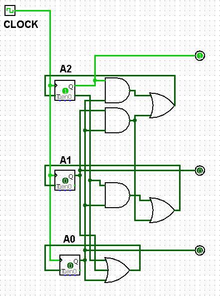
Implementation in logisim:
Hope this helps
Thank You
Add Answer to:
Need help understanding and doing this type of problem. Will upvote
for clear instructions, please! (parts...
Its logic design my sequence is 127605 i need help with all this pages please and thank you
 Its logic design
my sequence is 127605
i need help with all this pages please and thank you
27 60 Experiment 4 Six-State Up-Down Counter 1 Objective To become familiar with the design procedures of a counter, which are applicable to the design of other synchronous sequential circuits. 2 Problem description A six-state up-down counter is to be designed. Three flip-flops with outputs Q2,Qi and Qo are required in the design. As shown in Figure 1, the counter is initialized...
Its logic design
my sequence is 127605
i need help with all this pages please and thank you
27 60 Experiment 4 Six-State Up-Down Counter 1 Objective To become familiar with the design procedures of a counter, which are applicable to the design of other synchronous sequential circuits. 2 Problem description A six-state up-down counter is to be designed. Three flip-flops with outputs Q2,Qi and Qo are required in the design. As shown in Figure 1, the counter is initialized...
14. Design a cyclic counter that produces the binary sequence 0, 2, 3,1. o..if the control signal...
 14?
14. Design a cyclic counter that produces the binary sequence 0, 2, 3,1. o..if the control signal X is 0 but produces the binary sequence 0, 1,3,2.0, if the control signal X is1.Use D flip-flops. (a) Draw the state diagram; (6 points (b) Draw the input, present state-next state, excitation table: (6 points) (c) Derive the minimal SOP expressions for the D inputs of the flip-flops using K-maps. Draw the logic circuit realization of the counter, using only NAND...
14?
14. Design a cyclic counter that produces the binary sequence 0, 2, 3,1. o..if the control signal X is 0 but produces the binary sequence 0, 1,3,2.0, if the control signal X is1.Use D flip-flops. (a) Draw the state diagram; (6 points (b) Draw the input, present state-next state, excitation table: (6 points) (c) Derive the minimal SOP expressions for the D inputs of the flip-flops using K-maps. Draw the logic circuit realization of the counter, using only NAND...
Design a three-bit counter using D flip-flops that has the following characteristics: When the value of...
 Design a three-bit counter using D flip-flops that has the following characteristics: When the value of an input x is 0, the counter counts "down" in standard order. When the value of x is 1, the counter counts "up" in standard order a. First, complete the state table shown below Present State Next State Excitation 0 0 0 0 0 0 1 0 0 0 0 0 0 b. Next, derive the logic equations using the Karnaugh maps shown below...
6. Design a 2-bit binary counter that counts, 0, 1, 2, 3, 0,. Use the 74LS374 IC, which has eight D flip-flops on it. They are positive-edge triggered, but it will not matter at all here You may draw...
 6. Design a 2-bit binary counter that counts, 0, 1, 2, 3, 0,. Use the 74LS374 IC, which has eight D flip-flops on it. They are positive-edge triggered, but it will not matter at all here You may draw a state diagram and then fill in the table Present State Q(t) Next State (D(t) - Q(t+1)) Q1(t) Qo(t) 7. Design a BCD binary counter that counts from 0 to 9 then back to 0 and repeat, displaying the count on...
Design a 3-bit counter that has only one input, w. It counts down 7, 6,5,... 0, 7,.. whenever w-0...
 all please
Design a 3-bit counter that has only one input, w. It counts down 7, 6,5,... 0, 7,.. whenever w-0, and counts up 0,1,2...7,0... when w 1 The output z-1, when the state of the counter is a prime number. Otherwise, z-0 1. List Inputs, Outputs and the count sequence. (5pts) 2. Draw the finite State machine for the counter. (10pts) 3. Draw the state transition table <extra columns for the flip flops values> (20pts) armed resource/content/1/case%20study.template.docx 4. Design...
all please
Design a 3-bit counter that has only one input, w. It counts down 7, 6,5,... 0, 7,.. whenever w-0, and counts up 0,1,2...7,0... when w 1 The output z-1, when the state of the counter is a prime number. Otherwise, z-0 1. List Inputs, Outputs and the count sequence. (5pts) 2. Draw the finite State machine for the counter. (10pts) 3. Draw the state transition table <extra columns for the flip flops values> (20pts) armed resource/content/1/case%20study.template.docx 4. Design...
Design a synchronous counter that counts up 0, 1, 2, 3, 0, 1, 2, 3, ......
Design a synchronous counter that counts up 0, 1, 2, 3, 0, 1, 2, 3, ... when an input x = 1, and down when x = 0 using (a) D flip-flops. (b) J-K flip-flops. You need to show the state definition table, the state transition diagram, the state transition table, the K-maps for the respective logic functions and the schematic of the implementation using flipflops and logic gates in (a) as well as the K-maps for the logic functions...
(a) Design an asynchronous Binary Coded Decimal (BCD) count-up counter using JK flip-flops. Draw the counter circuit clearly showing the configuration of the JK flip-flops and the necessary logic gat...
 (a) Design an asynchronous Binary Coded Decimal (BCD) count-up counter using JK flip-flops. Draw the counter circuit clearly showing the configuration of the JK flip-flops and the necessary logic gate(s). Sketch the input and output waveforms of this counter (7 Marks) (b) The binary up/down counter for a cargo lift controller in a 7-storey building has an up-down (UID) control input and a buzzer output (B). The buzzer will sound B 1) when the lift is at level 1 or...
bilbecome famillar with t Objective design of other smchronos e pieos 2A Problem description six-state up-down...
 bilbecome famillar with t Objective design of other smchronos e pieos 2A Problem description six-state up-down co and Qo are required in the desidesi are rotvpulse to the REETInuo a posal state Se where the normal countet direcion Te the circuit in the initial st the RES hown in Fres flip-opw wi the RESET input is O during KESET Input of the couner th counting sequence is signal Cwa reversed irc- s an up-counter. The RES So 0. Ss S4...
Problem 3:(10 pts) Design a synchronous machine (Transition Table, K-maps, Final Equations, Circu...
 Problem 3:(10 pts) Design a synchronous machine (Transition Table, K-maps, Final Equations, Circuit Diagram) that counts through the following sequence in the order shown below. Note, there are no inputs or output variables, so your Q values must reflect the Hex value listed B 742 D 9 3 0 and repeat a) using all D flip-flops and combinational logic (AND/OR/NOT gates only) b) using all T flip-flops and a multiplexer of size 8:1
Problem 3:(10 pts) Design a synchronous machine...
Problem 3:(10 pts) Design a synchronous machine (Transition Table, K-maps, Final Equations, Circuit Diagram) that counts through the following sequence in the order shown below. Note, there are no inputs or output variables, so your Q values must reflect the Hex value listed B 742 D 9 3 0 and repeat a) using all D flip-flops and combinational logic (AND/OR/NOT gates only) b) using all T flip-flops and a multiplexer of size 8:1
Problem 3:(10 pts) Design a synchronous machine...
Design a two-bit up/down binary counter using D flip-flops that can count in binary from 0 to 7.
Design a two-bit up/down binary counter using D flip-flops that can count in binary from 0 to 7. When the control input x is 0, the circuit counts down, and when it is 1, the circuit counts up. (a) Obtain the state table of the two-bit counter. (b) Obtain the state diagram (c) Draw the logic diagram of the circuit.
 Its logic design
my sequence is 127605
i need help with all this pages please and thank you
27 60 Experiment 4 Six-State Up-Down Counter 1 Objective To become familiar with the design procedures of a counter, which are applicable to the design of other synchronous sequential circuits. 2 Problem description A six-state up-down counter is to be designed. Three flip-flops with outputs Q2,Qi and Qo are required in the design. As shown in Figure 1, the counter is initialized...
Its logic design
my sequence is 127605
i need help with all this pages please and thank you
27 60 Experiment 4 Six-State Up-Down Counter 1 Objective To become familiar with the design procedures of a counter, which are applicable to the design of other synchronous sequential circuits. 2 Problem description A six-state up-down counter is to be designed. Three flip-flops with outputs Q2,Qi and Qo are required in the design. As shown in Figure 1, the counter is initialized...
 14?
14. Design a cyclic counter that produces the binary sequence 0, 2, 3,1. o..if the control signal X is 0 but produces the binary sequence 0, 1,3,2.0, if the control signal X is1.Use D flip-flops. (a) Draw the state diagram; (6 points (b) Draw the input, present state-next state, excitation table: (6 points) (c) Derive the minimal SOP expressions for the D inputs of the flip-flops using K-maps. Draw the logic circuit realization of the counter, using only NAND...
14?
14. Design a cyclic counter that produces the binary sequence 0, 2, 3,1. o..if the control signal X is 0 but produces the binary sequence 0, 1,3,2.0, if the control signal X is1.Use D flip-flops. (a) Draw the state diagram; (6 points (b) Draw the input, present state-next state, excitation table: (6 points) (c) Derive the minimal SOP expressions for the D inputs of the flip-flops using K-maps. Draw the logic circuit realization of the counter, using only NAND...
 Design a three-bit counter using D flip-flops that has the following characteristics: When the value of an input x is 0, the counter counts "down" in standard order. When the value of x is 1, the counter counts "up" in standard order a. First, complete the state table shown below Present State Next State Excitation 0 0 0 0 0 0 1 0 0 0 0 0 0 b. Next, derive the logic equations using the Karnaugh maps shown below...
 6. Design a 2-bit binary counter that counts, 0, 1, 2, 3, 0,. Use the 74LS374 IC, which has eight D flip-flops on it. They are positive-edge triggered, but it will not matter at all here You may draw a state diagram and then fill in the table Present State Q(t) Next State (D(t) - Q(t+1)) Q1(t) Qo(t) 7. Design a BCD binary counter that counts from 0 to 9 then back to 0 and repeat, displaying the count on...
 all please
Design a 3-bit counter that has only one input, w. It counts down 7, 6,5,... 0, 7,.. whenever w-0, and counts up 0,1,2...7,0... when w 1 The output z-1, when the state of the counter is a prime number. Otherwise, z-0 1. List Inputs, Outputs and the count sequence. (5pts) 2. Draw the finite State machine for the counter. (10pts) 3. Draw the state transition table <extra columns for the flip flops values> (20pts) armed resource/content/1/case%20study.template.docx 4. Design...
all please
Design a 3-bit counter that has only one input, w. It counts down 7, 6,5,... 0, 7,.. whenever w-0, and counts up 0,1,2...7,0... when w 1 The output z-1, when the state of the counter is a prime number. Otherwise, z-0 1. List Inputs, Outputs and the count sequence. (5pts) 2. Draw the finite State machine for the counter. (10pts) 3. Draw the state transition table <extra columns for the flip flops values> (20pts) armed resource/content/1/case%20study.template.docx 4. Design...
 (a) Design an asynchronous Binary Coded Decimal (BCD) count-up counter using JK flip-flops. Draw the counter circuit clearly showing the configuration of the JK flip-flops and the necessary logic gate(s). Sketch the input and output waveforms of this counter (7 Marks) (b) The binary up/down counter for a cargo lift controller in a 7-storey building has an up-down (UID) control input and a buzzer output (B). The buzzer will sound B 1) when the lift is at level 1 or...
 bilbecome famillar with t Objective design of other smchronos e pieos 2A Problem description six-state up-down co and Qo are required in the desidesi are rotvpulse to the REETInuo a posal state Se where the normal countet direcion Te the circuit in the initial st the RES hown in Fres flip-opw wi the RESET input is O during KESET Input of the couner th counting sequence is signal Cwa reversed irc- s an up-counter. The RES So 0. Ss S4...
 Problem 3:(10 pts) Design a synchronous machine (Transition Table, K-maps, Final Equations, Circuit Diagram) that counts through the following sequence in the order shown below. Note, there are no inputs or output variables, so your Q values must reflect the Hex value listed B 742 D 9 3 0 and repeat a) using all D flip-flops and combinational logic (AND/OR/NOT gates only) b) using all T flip-flops and a multiplexer of size 8:1
Problem 3:(10 pts) Design a synchronous machine...
Problem 3:(10 pts) Design a synchronous machine (Transition Table, K-maps, Final Equations, Circuit Diagram) that counts through the following sequence in the order shown below. Note, there are no inputs or output variables, so your Q values must reflect the Hex value listed B 742 D 9 3 0 and repeat a) using all D flip-flops and combinational logic (AND/OR/NOT gates only) b) using all T flip-flops and a multiplexer of size 8:1
Problem 3:(10 pts) Design a synchronous machine...
Most questions answered within 3 hours.
-
Where is the error in this code sequence?
String s1 = "Hello";
String s2 = "ello";...
asked 10 months ago -
Financial data for Joel de Paris, Inc., for last year
follow:
Joel de Paris, Inc.
Balance...
asked 10 months ago -
Consider this reaction:
Al2(SO4)3 (aq)+ BaCl3
(aq) Al2Cl6 (aq)- +
3BaSO4(s) . What is the...
asked 10 months ago -
Suppose that Savneet is considering increasing her
recent random sample from 20 car rentals to 40...
asked 10 months ago -
Trucks arrive at an unloading terminal at an average rate of 120
per hour.
Trucks arrive...
asked 10 months ago -
Why are methanol and ethanol completely soluble in water while
octanol is not very little soluble....
asked 10 months ago -
A facilities manager at a university reads in a research report
that the mean amount of...
asked 10 months ago -
When the CuSO4 is rehydrated by adding water to the anhydrous
compound, is this an endothermic...
asked 10 months ago -
A ray of sunlight is passing from diamond into crown glass; the
angle of incidence is...
asked 10 months ago -
A block of mass 0.249 kg is placed on top of a light, vertical
spring of...
asked 10 months ago -
how do the kidneys compensate in the presences of acidosis
a) trigger hyperventilate
b) reserve acid...
asked 10 months ago -
Question 501 pts
The rental rate of capital to the firm increases. Which of the
following...
asked 10 months ago