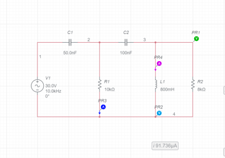
Q1: What is the total impedance of the circuit?
Q2: At what AC source frequency the voltage and the current in the circuit are in phase?
Homework Answers
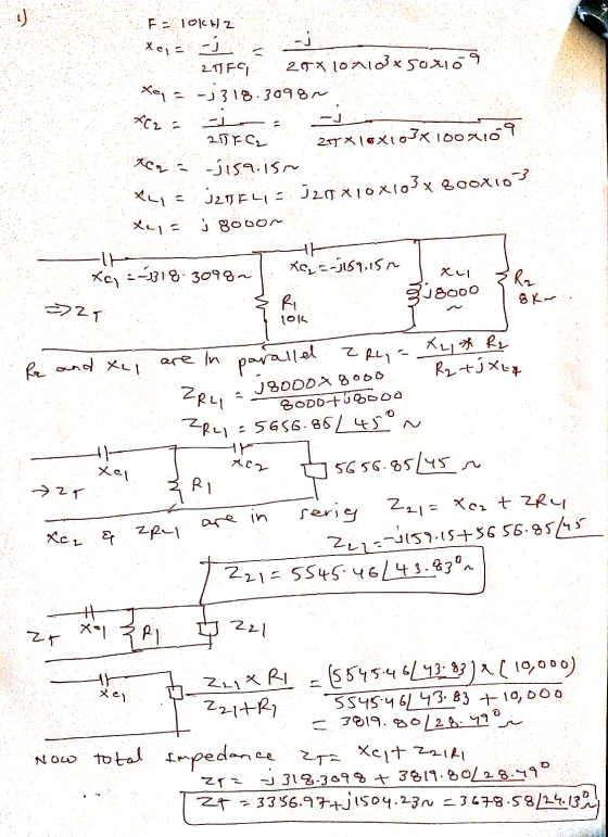
Add Answer to:
Q1: What is the total impedance of the circuit?
Q2: At what AC source frequency the...
Q: Calculate the amount of phase difference between the source voltage and the current in the...
 Q: Calculate the amount of phase difference between the source
voltage and the current in the circuit.
PR3 v 280.17mV R1 PR2 PR1 11,266.82htv v-273.71mV 1002 100m 3 V1 C1 1V 10kHz 0° 4 10uF
Q: Calculate the amount of phase difference between the source
voltage and the current in the circuit.
PR3 v 280.17mV R1 PR2 PR1 11,266.82htv v-273.71mV 1002 100m 3 V1 C1 1V 10kHz 0° 4 10uF
Consider the circuit as shown below. R-2 92 Use Kirchoff's rules to calculate (a) the current...
 Consider the circuit as shown below. R-2 92 Use Kirchoff's rules to calculate (a) the current through each resistor: Le. R1: [IR1] A R2: [IR2] A R3: [IR3] A R4: [IR4] A (b) the power supplied by each DC source;i.e. V1: [P1] Watts v2: [P2] Watts v3: [P3] Watts and (c) the power dissipated in each resistor; L.e. R1: [PR1] Watts R2: [PR2] Watts R3: [PR3] watts R4: [PR4] watts IR1 is equal to ?? Amps Answer: IR2 is equal...
For the circuit below, what is the total impedance as seen by the source at 140...
 For the circuit below, what is the total impedance as seen by the source at 140 Hz? Give your answer in terms of magnitude (ohms) and phase (degrees or radians), 1. Is the circuit more capacitive or inductive? What is the resonant frequency? what is the total current? Give both magnitude and phase-一一 R3 R1 140 Hz C1 V1 0° し1 100mH
Problem 2: In the circuit on Figure P2, BJT NPN Q1 and Q2 emulate a Darlington...
 Problem 2: In the circuit on Figure P2, BJT NPN Q1 and Q2 emulate a Darlington Pair (DP). It should be noted that Q1 and Q2 are such that their current gains are B1 B2 = B = 99. Moreover, capacitors C1 and C2 can be assumed to be very large. Note: The DC analysis of the DP circuit below can be done in a similar fashion as what you do when only dealing with one transistor. Express the current...
AC sweep Q1: What is the attenuation in dB for the RC filter at 100k Hz?...
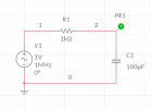 AC sweep
Q1: What is the attenuation in dB for the RC filter at 100k
Hz?
Q2: What is the phase at 100 Hz? (Read on your plot)
PR1 R1 1 N V 1kΩ V1 C1 17 1MHz 0° 100uF 0
AC sweep
Q1: What is the attenuation in dB for the RC filter at 100k
Hz?
Q2: What is the phase at 100 Hz? (Read on your plot)
PR1 R1 1 N V 1kΩ V1 C1 17 1MHz 0° 100uF 0
3 Circuit C2 R1 Connect to Vo Unity Gair 470 0.1uF Follower Ground Output C1 4700 R2 R3 1000 C3 luF Figure 1. AC Test C...
 3 Circuit C2 R1 Connect to Vo Unity Gair 470 0.1uF Follower Ground Output C1 4700 R2 R3 1000 C3 luF Figure 1. AC Test Circuit. 5 LTspice Simulation » Use LTspice to simulate the circuit shown in Figure 1. . The AC voltage source should have an amplitude of 5V and a frequency of 60Hz. When you enter the parameters in LTspice, you should see them displayed on the schematic as follows SINE(0 5 60000 1000) * Graph the...
3. Consider the AC circuit shown in the figure below, consisting of an alternating voltage source—of...
 3. Consider the AC circuit shown in the figure below, consisting
of an alternating voltage source—of voltage V (t) = V0 cos (ωt)—a
capacitor (of capacitance C), an inductor (of inductance L), and
two resistors (of resistances R1 and R2). Also, note the
highlighted points a and b in the circuit. (a) While explaining
your reasoning, determine the necessary condition that must be
satisfied between the circuit elements such that the potential
difference between points a and b is zero...
3. Consider the AC circuit shown in the figure below, consisting
of an alternating voltage source—of voltage V (t) = V0 cos (ωt)—a
capacitor (of capacitance C), an inductor (of inductance L), and
two resistors (of resistances R1 and R2). Also, note the
highlighted points a and b in the circuit. (a) While explaining
your reasoning, determine the necessary condition that must be
satisfied between the circuit elements such that the potential
difference between points a and b is zero...
R1 C1 HH The V1 R2 11 R3 circuit shown is a simplified representation of a...
 R1 C1 HH The V1 R2 11 R3 circuit shown is a simplified representation of a small signal transistor amplifier circuit. The AC input voltage is V1, with angular frequency w. The current through R2, is It. The dependent current source, 11, has value 100 IV. Let R1 = 500, and R2 = 1000. The load resistor, R3 has a value that is selectable by a design engineer. Let C1 = 10 pF, and L1 = 1 uH. (For reference,...
multisim help Part II: Capacitors in AC Circuits In this part, you will determine the impedance...
 multisim help
Part II: Capacitors in AC Circuits In this part, you will determine the impedance of the circuit at various frequencies. The capacitive reactance is calculated using Xc = Vc/Ic 1- Construct the circuit of Figure 9.2. Connect meters to measure voltage and current. R1 mA 1kohm C1 AC 3.3uF Figure 9.2-Circuit to Determine Capacitive Reactance 2- Set the voltage to 6Vrms at 60Hz. Measure and record values in Table 9.3. Calculate reactance using Xc = 1/(2nf C) and...
multisim help
Part II: Capacitors in AC Circuits In this part, you will determine the impedance of the circuit at various frequencies. The capacitive reactance is calculated using Xc = Vc/Ic 1- Construct the circuit of Figure 9.2. Connect meters to measure voltage and current. R1 mA 1kohm C1 AC 3.3uF Figure 9.2-Circuit to Determine Capacitive Reactance 2- Set the voltage to 6Vrms at 60Hz. Measure and record values in Table 9.3. Calculate reactance using Xc = 1/(2nf C) and...
A series circuit consists of an AC source of variable frequency, a 115 Ohm resistor, a...
A series circuit consists of an AC source of variable frequency, a 115Ω resistor, a 1.25 μF capacitor, and a 4.50 mH inductor. Find the impedance of this circuit when the angular frequency of the ac source is adjusted to (a) the resonance angular frequency; (b) twice the resonance angular frequency. If the power source provides a peak voltage of 60 V. what ore (c) the peak current in the circuit and (d) the average power dissipated in the circuit...
 Q: Calculate the amount of phase difference between the source
voltage and the current in the circuit.
PR3 v 280.17mV R1 PR2 PR1 11,266.82htv v-273.71mV 1002 100m 3 V1 C1 1V 10kHz 0° 4 10uF
Q: Calculate the amount of phase difference between the source
voltage and the current in the circuit.
PR3 v 280.17mV R1 PR2 PR1 11,266.82htv v-273.71mV 1002 100m 3 V1 C1 1V 10kHz 0° 4 10uF
 Consider the circuit as shown below. R-2 92 Use Kirchoff's rules to calculate (a) the current through each resistor: Le. R1: [IR1] A R2: [IR2] A R3: [IR3] A R4: [IR4] A (b) the power supplied by each DC source;i.e. V1: [P1] Watts v2: [P2] Watts v3: [P3] Watts and (c) the power dissipated in each resistor; L.e. R1: [PR1] Watts R2: [PR2] Watts R3: [PR3] watts R4: [PR4] watts IR1 is equal to ?? Amps Answer: IR2 is equal...
 For the circuit below, what is the total impedance as seen by the source at 140 Hz? Give your answer in terms of magnitude (ohms) and phase (degrees or radians), 1. Is the circuit more capacitive or inductive? What is the resonant frequency? what is the total current? Give both magnitude and phase-一一 R3 R1 140 Hz C1 V1 0° し1 100mH
 Problem 2: In the circuit on Figure P2, BJT NPN Q1 and Q2 emulate a Darlington Pair (DP). It should be noted that Q1 and Q2 are such that their current gains are B1 B2 = B = 99. Moreover, capacitors C1 and C2 can be assumed to be very large. Note: The DC analysis of the DP circuit below can be done in a similar fashion as what you do when only dealing with one transistor. Express the current...
 AC sweep
Q1: What is the attenuation in dB for the RC filter at 100k
Hz?
Q2: What is the phase at 100 Hz? (Read on your plot)
PR1 R1 1 N V 1kΩ V1 C1 17 1MHz 0° 100uF 0
AC sweep
Q1: What is the attenuation in dB for the RC filter at 100k
Hz?
Q2: What is the phase at 100 Hz? (Read on your plot)
PR1 R1 1 N V 1kΩ V1 C1 17 1MHz 0° 100uF 0
 3 Circuit C2 R1 Connect to Vo Unity Gair 470 0.1uF Follower Ground Output C1 4700 R2 R3 1000 C3 luF Figure 1. AC Test Circuit. 5 LTspice Simulation » Use LTspice to simulate the circuit shown in Figure 1. . The AC voltage source should have an amplitude of 5V and a frequency of 60Hz. When you enter the parameters in LTspice, you should see them displayed on the schematic as follows SINE(0 5 60000 1000) * Graph the...
 3. Consider the AC circuit shown in the figure below, consisting
of an alternating voltage source—of voltage V (t) = V0 cos (ωt)—a
capacitor (of capacitance C), an inductor (of inductance L), and
two resistors (of resistances R1 and R2). Also, note the
highlighted points a and b in the circuit. (a) While explaining
your reasoning, determine the necessary condition that must be
satisfied between the circuit elements such that the potential
difference between points a and b is zero...
3. Consider the AC circuit shown in the figure below, consisting
of an alternating voltage source—of voltage V (t) = V0 cos (ωt)—a
capacitor (of capacitance C), an inductor (of inductance L), and
two resistors (of resistances R1 and R2). Also, note the
highlighted points a and b in the circuit. (a) While explaining
your reasoning, determine the necessary condition that must be
satisfied between the circuit elements such that the potential
difference between points a and b is zero...
 R1 C1 HH The V1 R2 11 R3 circuit shown is a simplified representation of a small signal transistor amplifier circuit. The AC input voltage is V1, with angular frequency w. The current through R2, is It. The dependent current source, 11, has value 100 IV. Let R1 = 500, and R2 = 1000. The load resistor, R3 has a value that is selectable by a design engineer. Let C1 = 10 pF, and L1 = 1 uH. (For reference,...
 multisim help
Part II: Capacitors in AC Circuits In this part, you will determine the impedance of the circuit at various frequencies. The capacitive reactance is calculated using Xc = Vc/Ic 1- Construct the circuit of Figure 9.2. Connect meters to measure voltage and current. R1 mA 1kohm C1 AC 3.3uF Figure 9.2-Circuit to Determine Capacitive Reactance 2- Set the voltage to 6Vrms at 60Hz. Measure and record values in Table 9.3. Calculate reactance using Xc = 1/(2nf C) and...
multisim help
Part II: Capacitors in AC Circuits In this part, you will determine the impedance of the circuit at various frequencies. The capacitive reactance is calculated using Xc = Vc/Ic 1- Construct the circuit of Figure 9.2. Connect meters to measure voltage and current. R1 mA 1kohm C1 AC 3.3uF Figure 9.2-Circuit to Determine Capacitive Reactance 2- Set the voltage to 6Vrms at 60Hz. Measure and record values in Table 9.3. Calculate reactance using Xc = 1/(2nf C) and...
Most questions answered within 3 hours.
-
Where is the error in this code sequence?
String s1 = "Hello";
String s2 = "ello";...
asked 11 months ago -
Financial data for Joel de Paris, Inc., for last year
follow:
Joel de Paris, Inc.
Balance...
asked 11 months ago -
Consider this reaction:
Al2(SO4)3 (aq)+ BaCl3
(aq) Al2Cl6 (aq)- +
3BaSO4(s) . What is the...
asked 11 months ago -
Suppose that Savneet is considering increasing her
recent random sample from 20 car rentals to 40...
asked 11 months ago -
Trucks arrive at an unloading terminal at an average rate of 120
per hour.
Trucks arrive...
asked 11 months ago -
Why are methanol and ethanol completely soluble in water while
octanol is not very little soluble....
asked 11 months ago -
A facilities manager at a university reads in a research report
that the mean amount of...
asked 11 months ago -
When the CuSO4 is rehydrated by adding water to the anhydrous
compound, is this an endothermic...
asked 11 months ago -
A ray of sunlight is passing from diamond into crown glass; the
angle of incidence is...
asked 11 months ago -
A block of mass 0.249 kg is placed on top of a light, vertical
spring of...
asked 11 months ago -
how do the kidneys compensate in the presences of acidosis
a) trigger hyperventilate
b) reserve acid...
asked 11 months ago -
Question 501 pts
The rental rate of capital to the firm increases. Which of the
following...
asked 11 months ago