
Homework Answers

Q2. For the op-amp circuit as shown below, given that RS = 49.5 k, RL =...
 Q2. For the op-amp circuit as shown below, given that RS = 49.5 k, RL = 12 k 2, R1 = 10 kO, R2 = 9 ㏀, R3 = 7.5 ko, R4 = 5 ㏀R5 = 2.2 k2 Ry vo Ry Ri Rs (a) Determine the voltage gain G1-vo1/vs: Submit Answer Tries o/5 (b) Determine the voltage gain G2-vo/vs: Submit Answer Tries o/5 Q3. For the op-amp circuit shown below, find the value of VO, where R1 = 20 Ω,...
An amplifier circuit is shown in Fig. 1b. The operational amplifier (op-amp) Ai can be assumed...
 An amplifier circuit is shown in Fig. 1b. The operational amplifier (op-amp) Ai can be assumed as ideal. The input impedance of this amplifier is 1M2. The gain of this amplifier is -100. R2 V R VVV 小小 Ri Fig. 1b (a) Show that 12 = (b) Find the expression of the voltage gain, Av, in terms Ri, R, R3 and R4. (c) Due to practical reasons, the maximum value to be used for the resistors is set at 1M2....
30 points) Consider the circuit in Fig. 3, in which V, 48V, R -10k2, R2 =...
 30 points) Consider the circuit in Fig. 3, in which V, 48V, R -10k2, R2 = 5K2 , R3 = 100K, and R4-50M. The Zener has a ½-3V and internal resistance Rz 100Ω . What is the output voltage over the load R1 for RL=100kΩ? R1 R3 Fig. 3
1. Connect the circuit shown in Figure 23. The values of the resistors are given below...
 1. Connect the circuit shown in Figure 23. The values of the resistors are given below in Table and the source voltage (vs) is 20 V. Ri R4 R5 Figure 23 - General Resistive Circuit R 4.7 ko Rz 15 k22 | Rz 10 k R4 22 ke | Rs 6.8 ko Table 6 - Values of Resistors 2. Calculate all the component currents (i, through is), all the component voltages (Vị through vs) using circuit theories you have learned...
Problem 7 (CLO 3, 4, 11 - Ideal Op-Amps, Design): We will now design an Op-Amp...
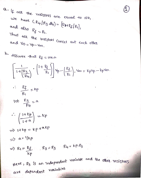
 Problem 7 (CLO 3, 4, 11 - Ideal Op-Amps, Design): We will now design an Op-Amp circuit to perform the function where v1 - input voltage 1, input voltage 2, = input voltage 3, Vo = output voltage. It may be helpful to consult your recitation 6 (week 7) results as well as Table 4-3 for this problem. 7.a: Select an Op-Amp configuration for your design. Sketch the Op-Amp configuration with symbolic resistors (Rf, Ri, R2, etc) indicated. Do not...
Problem 5. The parameters of the two inverting op-amp circuits connected in cascade, shown below, are...
 Problem 5. The parameters of the two inverting op-amp circuits connected in cascade, shown below, are R1 10 kQ, R2 80 k, R3 20 ko, and R4 100 kQ. For Vi0.15 V, determine Vo1, Vo, i,, i2, i3, and i4 Also, determine the current into or out of the output terminal of each op-amp. Rs
A circuit is constructed with six resistors and two batteries as shown The battery voltages are V1=18 V and V2=12 V.
 A circuit is constructed with six resistors and two batteries as shown The battery voltages are V1=18 V and V2=12 V. The positive terminals are indicated with a + sign, The values for the resistors are: R1=R5=66 Ω, R2=R6=83 Ω R3=55 Ω, and R4=69 Ω. The positive directions for the currents I1, I2 and I3 are indicated by the directions of the arrows.1) What is V4, the magnitude of the voltage across the resistor R4? 2) What is I3, the current...
The circuit shown has the following values for voltages and resistors: V1 13.0 V V2-12.0 V...
 The circuit shown has the following values for voltages and resistors: V1 13.0 V V2-12.0 V R1 5.65 Ohms R2-1.61 Ohms R3 4.82 Ohms R4 4.62 Ohms R5-5.05 Ohms R1 I, R2 R3 I, RA V2 Rs Determine the magnitude of current I1.
Assuming an ideal op-amp in the following circuit, find output voltage, Vo if R1= 2 K2,...
 Assuming an ideal op-amp in the following circuit, find output voltage, Vo if R1= 2 K2, R2=8 K2, R3=5.1 K2, R4=6 KN, R5=14 KN, R6=4.2 KS, RL=10.3 KS, V1=1V, 12=0.5 mA and V3=3.2 V. R6 R1 R5 Vo w + * RL + 12 R2 V1 R3 R4 V3 Answer: OV Using the above circuit, but consider the following component values: R1= 2 K12 R2=8 K2, R3=2.9 K2, R4=6 KI2, R5=10.8 K92, R6=15 KO, RL=10 K2, V1=1V, 12=0.5mA and V3=2V....
Assuming an ideal op-amp in the following circuit, find output voltage, Vo if R1= 2 K12,...
 Assuming an ideal op-amp in the following circuit, find output voltage, Vo if R1= 2 K12, R2=8 KN, R3=3.9 KN, R4=6 KN, R5=18 K2, R6=4.4 KN, RL=12.5 KN, V1=1V, 12=0.5 mA and V3=3.4 V. R6 R1 R5 Vo + + RL R2 V1 R3 R4 + V3 Answer: LOV Using the above circuit, but consider the following component values: R1= 2 KO2 R2=8 K12, R3=3.6 K12, R4=6 K12, R5=16.9 KN, R6=15 KN, RL=10 KO, V1=1V, 12=0.5mA and V3=2V. What is...
 Q2. For the op-amp circuit as shown below, given that RS = 49.5 k, RL = 12 k 2, R1 = 10 kO, R2 = 9 ㏀, R3 = 7.5 ko, R4 = 5 ㏀R5 = 2.2 k2 Ry vo Ry Ri Rs (a) Determine the voltage gain G1-vo1/vs: Submit Answer Tries o/5 (b) Determine the voltage gain G2-vo/vs: Submit Answer Tries o/5 Q3. For the op-amp circuit shown below, find the value of VO, where R1 = 20 Ω,...
 An amplifier circuit is shown in Fig. 1b. The operational amplifier (op-amp) Ai can be assumed as ideal. The input impedance of this amplifier is 1M2. The gain of this amplifier is -100. R2 V R VVV 小小 Ri Fig. 1b (a) Show that 12 = (b) Find the expression of the voltage gain, Av, in terms Ri, R, R3 and R4. (c) Due to practical reasons, the maximum value to be used for the resistors is set at 1M2....
 30 points) Consider the circuit in Fig. 3, in which V, 48V, R -10k2, R2 = 5K2 , R3 = 100K, and R4-50M. The Zener has a ½-3V and internal resistance Rz 100Ω . What is the output voltage over the load R1 for RL=100kΩ? R1 R3 Fig. 3
 1. Connect the circuit shown in Figure 23. The values of the resistors are given below in Table and the source voltage (vs) is 20 V. Ri R4 R5 Figure 23 - General Resistive Circuit R 4.7 ko Rz 15 k22 | Rz 10 k R4 22 ke | Rs 6.8 ko Table 6 - Values of Resistors 2. Calculate all the component currents (i, through is), all the component voltages (Vị through vs) using circuit theories you have learned...
 Problem 7 (CLO 3, 4, 11 - Ideal Op-Amps, Design): We will now design an Op-Amp circuit to perform the function where v1 - input voltage 1, input voltage 2, = input voltage 3, Vo = output voltage. It may be helpful to consult your recitation 6 (week 7) results as well as Table 4-3 for this problem. 7.a: Select an Op-Amp configuration for your design. Sketch the Op-Amp configuration with symbolic resistors (Rf, Ri, R2, etc) indicated. Do not...
 Problem 5. The parameters of the two inverting op-amp circuits connected in cascade, shown below, are R1 10 kQ, R2 80 k, R3 20 ko, and R4 100 kQ. For Vi0.15 V, determine Vo1, Vo, i,, i2, i3, and i4 Also, determine the current into or out of the output terminal of each op-amp. Rs
 The circuit shown has the following values for voltages and resistors: V1 13.0 V V2-12.0 V R1 5.65 Ohms R2-1.61 Ohms R3 4.82 Ohms R4 4.62 Ohms R5-5.05 Ohms R1 I, R2 R3 I, RA V2 Rs Determine the magnitude of current I1.
 Assuming an ideal op-amp in the following circuit, find output voltage, Vo if R1= 2 K2, R2=8 K2, R3=5.1 K2, R4=6 KN, R5=14 KN, R6=4.2 KS, RL=10.3 KS, V1=1V, 12=0.5 mA and V3=3.2 V. R6 R1 R5 Vo w + * RL + 12 R2 V1 R3 R4 V3 Answer: OV Using the above circuit, but consider the following component values: R1= 2 K12 R2=8 K2, R3=2.9 K2, R4=6 KI2, R5=10.8 K92, R6=15 KO, RL=10 K2, V1=1V, 12=0.5mA and V3=2V....
 Assuming an ideal op-amp in the following circuit, find output voltage, Vo if R1= 2 K12, R2=8 KN, R3=3.9 KN, R4=6 KN, R5=18 K2, R6=4.4 KN, RL=12.5 KN, V1=1V, 12=0.5 mA and V3=3.4 V. R6 R1 R5 Vo + + RL R2 V1 R3 R4 + V3 Answer: LOV Using the above circuit, but consider the following component values: R1= 2 KO2 R2=8 K12, R3=3.6 K12, R4=6 K12, R5=16.9 KN, R6=15 KN, RL=10 KO, V1=1V, 12=0.5mA and V3=2V. What is...
Most questions answered within 3 hours.
-
Where is the error in this code sequence?
String s1 = "Hello";
String s2 = "ello";...
asked 10 months ago -
Financial data for Joel de Paris, Inc., for last year
follow:
Joel de Paris, Inc.
Balance...
asked 10 months ago -
Consider this reaction:
Al2(SO4)3 (aq)+ BaCl3
(aq) Al2Cl6 (aq)- +
3BaSO4(s) . What is the...
asked 10 months ago -
Suppose that Savneet is considering increasing her
recent random sample from 20 car rentals to 40...
asked 10 months ago -
Trucks arrive at an unloading terminal at an average rate of 120
per hour.
Trucks arrive...
asked 10 months ago -
Why are methanol and ethanol completely soluble in water while
octanol is not very little soluble....
asked 10 months ago -
A facilities manager at a university reads in a research report
that the mean amount of...
asked 10 months ago -
When the CuSO4 is rehydrated by adding water to the anhydrous
compound, is this an endothermic...
asked 10 months ago -
A ray of sunlight is passing from diamond into crown glass; the
angle of incidence is...
asked 10 months ago -
A block of mass 0.249 kg is placed on top of a light, vertical
spring of...
asked 10 months ago -
how do the kidneys compensate in the presences of acidosis
a) trigger hyperventilate
b) reserve acid...
asked 10 months ago -
Question 501 pts
The rental rate of capital to the firm increases. Which of the
following...
asked 10 months ago