
Please answer question 1 thank you
Reinforced Concrete HW
Homework Answers
Add Answer to:
Please answer question 1 thank you
Reinforced Concrete HW
18%20(2).pdf CEE433- Homework Assignment 9 Assigned: 12...
Please answer question 1 thank you Reinforced Concrete HW 18%20(2).pdf CEE433- Homework Assignment 9 Assigned: 12...
 Please answer question 1 thank you
Reinforced Concrete HW
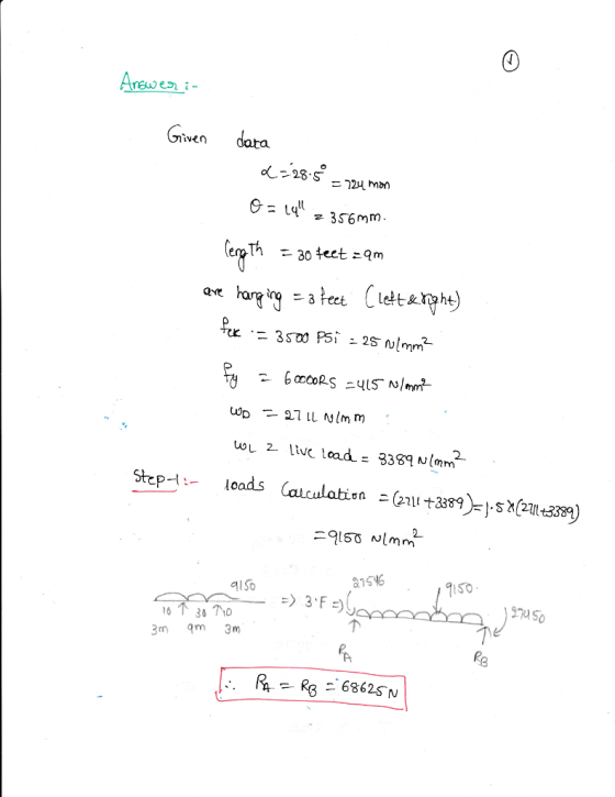
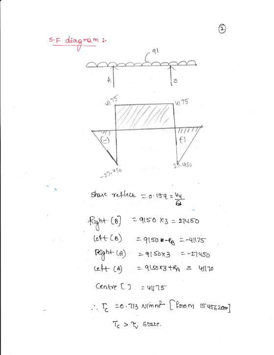
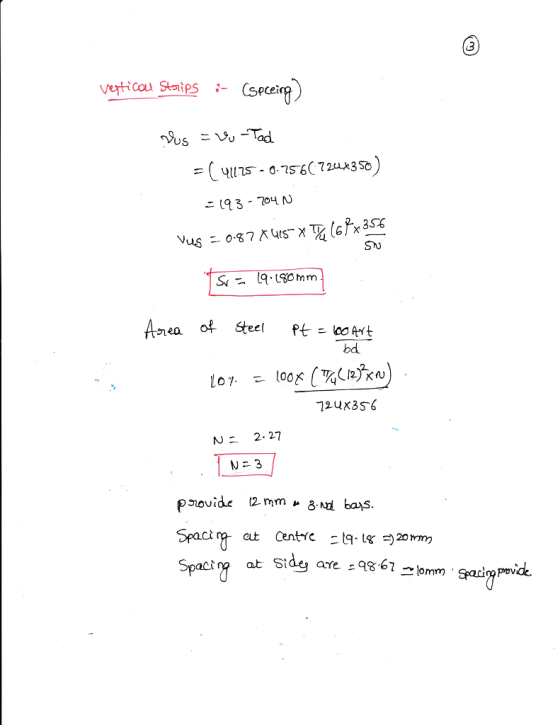
18%20(2).pdf CEE433- Homework Assignment 9 Assigned: 12 April 2018 Due: 19 April 2018 1. Design the shear reinforcement (vertical stirrups) for the beam shown in the figure. Design stirrups based on the shear envelope using the approximate procedure discussed in class. Note that for the overhangs the maximum shear at the support is induced by placing dead and live loads throughout the cantilever portion. Satisfy all strength and spacing requirements specified...
Please answer question 1 thank you
Reinforced Concrete HW
18%20(2).pdf CEE433- Homework Assignment 9 Assigned: 12 April 2018 Due: 19 April 2018 1. Design the shear reinforcement (vertical stirrups) for the beam shown in the figure. Design stirrups based on the shear envelope using the approximate procedure discussed in class. Note that for the overhangs the maximum shear at the support is induced by placing dead and live loads throughout the cantilever portion. Satisfy all strength and spacing requirements specified...
A reinforced concrete beam shown in Figure below is 15-in. wide and has effective depth of31 in. ...
 A reinforced concrete beam shown in Figure below is 15-in. wide and has effective depth of31 in. The factored loads are shown. (The factored uniform load includes the weight of the beam). Design the web reinforcement using the Vu diagram shown in the Figure (for a symmetric half). Assume No. 3 stirrups,fc '-4000 psi and fy=fyt-60000psi. 100 kip 100 kip d-31 in. 15 ft clear span As s) 102.5 kip se 2.5 ki @y、阪、もw cl.* 3..-K: ps
A reinforced concrete...
A reinforced concrete beam shown in Figure below is 15-in. wide and has effective depth of31 in. The factored loads are shown. (The factored uniform load includes the weight of the beam). Design the web reinforcement using the Vu diagram shown in the Figure (for a symmetric half). Assume No. 3 stirrups,fc '-4000 psi and fy=fyt-60000psi. 100 kip 100 kip d-31 in. 15 ft clear span As s) 102.5 kip se 2.5 ki @y、阪、もw cl.* 3..-K: ps
A reinforced concrete...
Design a reinforced concrete beam that has a rectangular cross section with a width b =...
Design a reinforced concrete beam that has a rectangular cross section with a width b = 24 in. The depth h is limited by architectural reasons to 16 in. It has to carry a factored moment Mu = 360 kip- ft. including the self-weight. The design should satisfy ACI 318 for tension controlled members. Use Grade 60 steel and a specified concrete compressive strength = 4,000 psi. Determine the flexural reinforcement for the beam, and use compression steel if needed....
20.0 30.0" 14 WL 2.5 k/ft Wo 1 k/ft 3.0", typ 3-#10 bars #3 stirrups 34,0" 2-#6 bars Column 1.5" cover...
 20.0 30.0" 14 WL 2.5 k/ft Wo 1 k/ft 3.0", typ 3-#10 bars #3 stirrups 34,0" 2-#6 bars Column 1.5" cover typ The cantilever beam shown is made of Class 4000 concrete and Grade 60 rebar. The dead load shown includes the beam self weight (d) (20%) Determine the maximum stirrup reinforcement spacing at the location of maximum shear. Utilize the member end shear reduction from ACI § 9.4.3.2 (and assume the requirements to use this provision are met)
20.0...
20.0 30.0" 14 WL 2.5 k/ft Wo 1 k/ft 3.0", typ 3-#10 bars #3 stirrups 34,0" 2-#6 bars Column 1.5" cover typ The cantilever beam shown is made of Class 4000 concrete and Grade 60 rebar. The dead load shown includes the beam self weight (d) (20%) Determine the maximum stirrup reinforcement spacing at the location of maximum shear. Utilize the member end shear reduction from ACI § 9.4.3.2 (and assume the requirements to use this provision are met)
20.0...
Please answer question 3. The dimensions are given in problem 1 thank you Reinforced Concrete df...
 Please answer question 3. The dimensions are given in problem 1
thank you
Reinforced Concrete
df Assigned: 20 February 2018 Due: 01 March 2018 1. For the rectangular cross section shown compute the nominal (M,) and design flexural strength (OM.) using the different reinforcement ratios corresponding to a net tensile strain of 0.002, 0.0025, 0.0030, 0.0035, 0.004, 0.0045, 0.005. Use f, = 60,000 psi and f', = 4,000 psi. Using these data points, plot M, and OM, as a function...
Please answer question 3. The dimensions are given in problem 1
thank you
Reinforced Concrete
df Assigned: 20 February 2018 Due: 01 March 2018 1. For the rectangular cross section shown compute the nominal (M,) and design flexural strength (OM.) using the different reinforcement ratios corresponding to a net tensile strain of 0.002, 0.0025, 0.0030, 0.0035, 0.004, 0.0045, 0.005. Use f, = 60,000 psi and f', = 4,000 psi. Using these data points, plot M, and OM, as a function...
. Deisgn a reinforced concrete cross-section with unknown dimensions Problem 1 Design the steel reinforcement for...
 . Deisgn a reinforced concrete cross-section with unknown dimensions Problem 1 Design the steel reinforcement for the beam shown in Figure 1 that supports its own self-weight, a uninformly distributed dead load, a uniformly distributed live load, and a live point load located at midspan. In your solution, you should select the area of reinforcement, the number and size of reinforcing bars, and the section depth in order to receive full credit. Assume J 5,000 psi, fy 60,000 psi. 16...
The T-beam shown in Figure 1 supports the un-factored dead load of 1.4 kips/ft and live...
 The T-beam shown in Figure 1 supports the un-factored dead load
of 1.4 kips/ft and live load of 1.5 kips/ft. The dead load does not
include the self-weight of the beam. The material properties are as
follows: fc’=3000 psi; fy=60,000 psi. Design the shear
reinforcement (stirrups). Plot the stirrups distribution along the
span of the beam.
DL= 1.4 kips/ft ; L2=1.5 kips/Ft * 75 Sz=7 X * b=3616. hr-6in k ) انا امه hw-lain + * bw=12 in
The T-beam shown in Figure 1 supports the un-factored dead load
of 1.4 kips/ft and live load of 1.5 kips/ft. The dead load does not
include the self-weight of the beam. The material properties are as
follows: fc’=3000 psi; fy=60,000 psi. Design the shear
reinforcement (stirrups). Plot the stirrups distribution along the
span of the beam.
DL= 1.4 kips/ft ; L2=1.5 kips/Ft * 75 Sz=7 X * b=3616. hr-6in k ) انا امه hw-lain + * bw=12 in
Please answer question 3 parts a,b,c thank you Reinforced Concrete HW 3. (40 pts) Analyze the...
 Please answer question 3 parts a,b,c thank you
Reinforced Concrete HW
3. (40 pts) Analyze the following statically determinate frame by hand and clearly draw the shear force, axial force, and bending moment diagrams indicating relevant (maximum and minimum) values for each of the following load cases: a) Uniform dead load (qo) applied on the beam – must add beam self-weight (concrete) to this value. b) Uniform live load (q) applied on the beam. c) Horizontal wind force (H). H=...
Please answer question 3 parts a,b,c thank you
Reinforced Concrete HW
3. (40 pts) Analyze the following statically determinate frame by hand and clearly draw the shear force, axial force, and bending moment diagrams indicating relevant (maximum and minimum) values for each of the following load cases: a) Uniform dead load (qo) applied on the beam – must add beam self-weight (concrete) to this value. b) Uniform live load (q) applied on the beam. c) Horizontal wind force (H). H=...
Problem 1 Reinforced Concrete T-Flanged Sections (50 pts.) You are required to analyze and design...
 Problem 1 Reinforced Concrete T-Flanged Sections (50 pts.) You are required to analyze and design the propped cantilever t-section from HM 4 but for shear only. Draw shear V and moment M diagrams for uniformly distributed load throughout the 30ft span and equally concentrated loads at 10ft and 30ft. Recall that the connection at the left joint N1 is fixed. The connection at 20ft N3 is a roller. The right end node N2 is a free end. Use a concrete...
Problem 1 Reinforced Concrete T-Flanged Sections (50 pts.) You are required to analyze and design...
 Problem 1 Reinforced Concrete T-Flanged Sections (50 pts.) You are required to analyze and design the propped cantilever t-section from HM 4 but for shear only. Draw shear V and moment M diagrams for uniformly distributed load throughout the 30ft span and equally concentrated loads at 10ft and 30ft. Recall that the connection at the left joint N1 is fixed. The connection at 20ft N3 is a roller. The right end node N2 is a free end. Usea concrete compressive...
 Please answer question 1 thank you
Reinforced Concrete HW
18%20(2).pdf CEE433- Homework Assignment 9 Assigned: 12 April 2018 Due: 19 April 2018 1. Design the shear reinforcement (vertical stirrups) for the beam shown in the figure. Design stirrups based on the shear envelope using the approximate procedure discussed in class. Note that for the overhangs the maximum shear at the support is induced by placing dead and live loads throughout the cantilever portion. Satisfy all strength and spacing requirements specified...
Please answer question 1 thank you
Reinforced Concrete HW
18%20(2).pdf CEE433- Homework Assignment 9 Assigned: 12 April 2018 Due: 19 April 2018 1. Design the shear reinforcement (vertical stirrups) for the beam shown in the figure. Design stirrups based on the shear envelope using the approximate procedure discussed in class. Note that for the overhangs the maximum shear at the support is induced by placing dead and live loads throughout the cantilever portion. Satisfy all strength and spacing requirements specified...
 A reinforced concrete beam shown in Figure below is 15-in. wide and has effective depth of31 in. The factored loads are shown. (The factored uniform load includes the weight of the beam). Design the web reinforcement using the Vu diagram shown in the Figure (for a symmetric half). Assume No. 3 stirrups,fc '-4000 psi and fy=fyt-60000psi. 100 kip 100 kip d-31 in. 15 ft clear span As s) 102.5 kip se 2.5 ki @y、阪、もw cl.* 3..-K: ps
A reinforced concrete...
A reinforced concrete beam shown in Figure below is 15-in. wide and has effective depth of31 in. The factored loads are shown. (The factored uniform load includes the weight of the beam). Design the web reinforcement using the Vu diagram shown in the Figure (for a symmetric half). Assume No. 3 stirrups,fc '-4000 psi and fy=fyt-60000psi. 100 kip 100 kip d-31 in. 15 ft clear span As s) 102.5 kip se 2.5 ki @y、阪、もw cl.* 3..-K: ps
A reinforced concrete...
 20.0 30.0" 14 WL 2.5 k/ft Wo 1 k/ft 3.0", typ 3-#10 bars #3 stirrups 34,0" 2-#6 bars Column 1.5" cover typ The cantilever beam shown is made of Class 4000 concrete and Grade 60 rebar. The dead load shown includes the beam self weight (d) (20%) Determine the maximum stirrup reinforcement spacing at the location of maximum shear. Utilize the member end shear reduction from ACI § 9.4.3.2 (and assume the requirements to use this provision are met)
20.0...
20.0 30.0" 14 WL 2.5 k/ft Wo 1 k/ft 3.0", typ 3-#10 bars #3 stirrups 34,0" 2-#6 bars Column 1.5" cover typ The cantilever beam shown is made of Class 4000 concrete and Grade 60 rebar. The dead load shown includes the beam self weight (d) (20%) Determine the maximum stirrup reinforcement spacing at the location of maximum shear. Utilize the member end shear reduction from ACI § 9.4.3.2 (and assume the requirements to use this provision are met)
20.0...
 Please answer question 3. The dimensions are given in problem 1
thank you
Reinforced Concrete
df Assigned: 20 February 2018 Due: 01 March 2018 1. For the rectangular cross section shown compute the nominal (M,) and design flexural strength (OM.) using the different reinforcement ratios corresponding to a net tensile strain of 0.002, 0.0025, 0.0030, 0.0035, 0.004, 0.0045, 0.005. Use f, = 60,000 psi and f', = 4,000 psi. Using these data points, plot M, and OM, as a function...
Please answer question 3. The dimensions are given in problem 1
thank you
Reinforced Concrete
df Assigned: 20 February 2018 Due: 01 March 2018 1. For the rectangular cross section shown compute the nominal (M,) and design flexural strength (OM.) using the different reinforcement ratios corresponding to a net tensile strain of 0.002, 0.0025, 0.0030, 0.0035, 0.004, 0.0045, 0.005. Use f, = 60,000 psi and f', = 4,000 psi. Using these data points, plot M, and OM, as a function...
 . Deisgn a reinforced concrete cross-section with unknown dimensions Problem 1 Design the steel reinforcement for the beam shown in Figure 1 that supports its own self-weight, a uninformly distributed dead load, a uniformly distributed live load, and a live point load located at midspan. In your solution, you should select the area of reinforcement, the number and size of reinforcing bars, and the section depth in order to receive full credit. Assume J 5,000 psi, fy 60,000 psi. 16...
 The T-beam shown in Figure 1 supports the un-factored dead load
of 1.4 kips/ft and live load of 1.5 kips/ft. The dead load does not
include the self-weight of the beam. The material properties are as
follows: fc’=3000 psi; fy=60,000 psi. Design the shear
reinforcement (stirrups). Plot the stirrups distribution along the
span of the beam.
DL= 1.4 kips/ft ; L2=1.5 kips/Ft * 75 Sz=7 X * b=3616. hr-6in k ) انا امه hw-lain + * bw=12 in
The T-beam shown in Figure 1 supports the un-factored dead load
of 1.4 kips/ft and live load of 1.5 kips/ft. The dead load does not
include the self-weight of the beam. The material properties are as
follows: fc’=3000 psi; fy=60,000 psi. Design the shear
reinforcement (stirrups). Plot the stirrups distribution along the
span of the beam.
DL= 1.4 kips/ft ; L2=1.5 kips/Ft * 75 Sz=7 X * b=3616. hr-6in k ) انا امه hw-lain + * bw=12 in
 Please answer question 3 parts a,b,c thank you
Reinforced Concrete HW
3. (40 pts) Analyze the following statically determinate frame by hand and clearly draw the shear force, axial force, and bending moment diagrams indicating relevant (maximum and minimum) values for each of the following load cases: a) Uniform dead load (qo) applied on the beam – must add beam self-weight (concrete) to this value. b) Uniform live load (q) applied on the beam. c) Horizontal wind force (H). H=...
Please answer question 3 parts a,b,c thank you
Reinforced Concrete HW
3. (40 pts) Analyze the following statically determinate frame by hand and clearly draw the shear force, axial force, and bending moment diagrams indicating relevant (maximum and minimum) values for each of the following load cases: a) Uniform dead load (qo) applied on the beam – must add beam self-weight (concrete) to this value. b) Uniform live load (q) applied on the beam. c) Horizontal wind force (H). H=...
 Problem 1 Reinforced Concrete T-Flanged Sections (50 pts.) You are required to analyze and design the propped cantilever t-section from HM 4 but for shear only. Draw shear V and moment M diagrams for uniformly distributed load throughout the 30ft span and equally concentrated loads at 10ft and 30ft. Recall that the connection at the left joint N1 is fixed. The connection at 20ft N3 is a roller. The right end node N2 is a free end. Use a concrete...
 Problem 1 Reinforced Concrete T-Flanged Sections (50 pts.) You are required to analyze and design the propped cantilever t-section from HM 4 but for shear only. Draw shear V and moment M diagrams for uniformly distributed load throughout the 30ft span and equally concentrated loads at 10ft and 30ft. Recall that the connection at the left joint N1 is fixed. The connection at 20ft N3 is a roller. The right end node N2 is a free end. Usea concrete compressive...
Most questions answered within 3 hours.
-
Where is the error in this code sequence?
String s1 = "Hello";
String s2 = "ello";...
asked 10 months ago -
Financial data for Joel de Paris, Inc., for last year
follow:
Joel de Paris, Inc.
Balance...
asked 10 months ago -
Consider this reaction:
Al2(SO4)3 (aq)+ BaCl3
(aq) Al2Cl6 (aq)- +
3BaSO4(s) . What is the...
asked 10 months ago -
Suppose that Savneet is considering increasing her
recent random sample from 20 car rentals to 40...
asked 10 months ago -
Trucks arrive at an unloading terminal at an average rate of 120
per hour.
Trucks arrive...
asked 10 months ago -
Why are methanol and ethanol completely soluble in water while
octanol is not very little soluble....
asked 10 months ago -
A facilities manager at a university reads in a research report
that the mean amount of...
asked 10 months ago -
When the CuSO4 is rehydrated by adding water to the anhydrous
compound, is this an endothermic...
asked 10 months ago -
A ray of sunlight is passing from diamond into crown glass; the
angle of incidence is...
asked 10 months ago -
A block of mass 0.249 kg is placed on top of a light, vertical
spring of...
asked 10 months ago -
how do the kidneys compensate in the presences of acidosis
a) trigger hyperventilate
b) reserve acid...
asked 10 months ago -
Question 501 pts
The rental rate of capital to the firm increases. Which of the
following...
asked 10 months ago