
Homework Answers


Add Answer to:
Chapter 13, Problem 4P Bookmark Show all steps: O ON Repeat Problem 1 using Coulomb's active...
its problem 17.6 on foundation engineering ninth edition by Braja M.Das 17.6 ung Coulomb's earth pressures....
 its problem 17.6 on foundation engineering ninth edition by
Braja M.Das
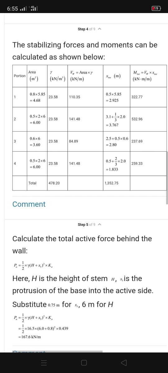
17.6 ung Coulomb's earth pressures. It is required to design a cantilever retaining wall to retain a 5.0 m high sandy backfill. The consultant suggests the dimensions and soil properties shown in Figure P17.6 and requires that the wall be checked for stability with respect to sliding and overturning based on the active earth pressures determined using 0.5 mm 110° EDT Sand y = 18.5 kN/m3 6' = 36°...
its problem 17.6 on foundation engineering ninth edition by
Braja M.Das
17.6 ung Coulomb's earth pressures. It is required to design a cantilever retaining wall to retain a 5.0 m high sandy backfill. The consultant suggests the dimensions and soil properties shown in Figure P17.6 and requires that the wall be checked for stability with respect to sliding and overturning based on the active earth pressures determined using 0.5 mm 110° EDT Sand y = 18.5 kN/m3 6' = 36°...
A gravity retaining wall is shown in figure. Use Rankine active earth pressure theory. Determine: a. The factor of safety against overturning b. The factor of safety against sliding c. The factor of safety for bearing capacity d. The pressure on the soil
 A gravity retaining wall is shown in figure. Use Rankine active earth pressure theory. Determine:a. The factor of safety against overturningb. The factor of safety against slidingc. The factor of safety for bearing capacityd. The pressure on the soil at the toe and heelAssume, γconcrete = 24 kN/m3. Also, consider the weight of the soil behind the wall and consider the passive earth pressure.
Figure 15.45 shows a gravity retaining wall retaining a granular (c' = 0) backfill. The same soil is present at the bottom of the wall and on the left. The unit weight and the friction angle of the backfill are 18.5 kN/m3 and 35°, respectively. The unit w
 Figure 15.45 shows a gravity retaining wall retaining a granular (c' = 0) backfill. The same soil is present at the bottom of the wall and on the left. The unit weight and the friction angle of the backfill are 18.5 kN/m3 and 35°, respectively. The unit weight of concrete is 24.0 kN/m3. Determine the factors of safety with respect to overturning, sliding, and bearing capacity failure. Use Rankine earth pressure theory.
Problem 1 For the cantilever retaining wall shown in Fig. 1, determine the factor of safety...
 Problem 1 For the cantilever retaining wall shown in Fig. 1, determine the factor of safety with respect to overturning, sliding, and bearing capacity. Use Rankine method to calculate the earth pressure. 18 in 100 Fig. 1 7 = 117 pcf (= 340 C = 0 4ft 30 in 6ft y = 110 pcf = 18 C = 800 psf
1 Calculate the factor of safety against overturning and sliding for the concrete retaining wall ...
 1 Calculate the factor of safety against overturning and sliding for the concrete retaining wall shown in the figure below, without taking into consideration the passive earth pressure. (50 Points) Assume that 115 lbs/cf unit weight of soil: unit weight of concrete: 150 lbs/cf angle of internal friction: 30 coefficient of friction: 0.350 0° B: 14 5' 2" Ha 14 2.5 Compaction (Soils engineering uses the symbol ys for dry density and uses the term dry unit weight. In the...
RCD3601/101/0/2019 QUESTION 8 Figura o shows the section through a neonased reinforced concrete cantilever retaining wall...
 RCD3601/101/0/2019 QUESTION 8 Figura o shows the section through a neonased reinforced concrete cantilever retaining wall that will be situated on a property boundary. Grade 30/19 concrete and high tensile steel reinforcement is to be The backfill behind the wall is sloping at an angle of 15º measured from the horizontal and is subjected to an imposed load of 2.5 kN/m². A geotechnical report gave the following soil parameters: • Unit weight of soil (V) = 17 kN/m • Angle...
Sove for part 1 CV 5263 HW 1 (2018-19) Name: Problem 2: Lateral Earth Pressure Theories...
 Sove for part 1
CV 5263 HW 1 (2018-19) Name: Problem 2: Lateral Earth Pressure Theories For both part 1 and part 2 determine: Magnitude of active resultant force per length of wall Location (height) of the active resultant force from the base of wall Direction (angle above horizontal) of the active resultant force Horizontal component of the active resultant force per length of wall Vertical component of the active resultant force per length of wall . Part 1: Coulomb...
Sove for part 1
CV 5263 HW 1 (2018-19) Name: Problem 2: Lateral Earth Pressure Theories For both part 1 and part 2 determine: Magnitude of active resultant force per length of wall Location (height) of the active resultant force from the base of wall Direction (angle above horizontal) of the active resultant force Horizontal component of the active resultant force per length of wall Vertical component of the active resultant force per length of wall . Part 1: Coulomb...
Question 2 (a) A 4 m high masonry retaining wall of width 1.8 is built to...
 Question 2 (a) A 4 m high masonry retaining wall of width 1.8 is built to retain a 2-layered soil profile shown in Figure 2 on Bonham Road on Hong Kong Island with a surface sucharge of 20 kPa. The soil parameters are given in the figure. During raining season, ground water rises to interface between Soil 1 and Soil 2. Assume that there is no friction between the vertical wall and the soils. The sliding friction angle between the...
Problem 2 130 points) A gravity cantilever wall is being designed to contain water in a canal, as shown in Figure 3.3 (Note: There is water only on the left side of the wall, there is no water un...
 Problem 2 130 points) A gravity cantilever wall is being designed to contain water in a canal, as shown in Figure 3.3 (Note: There is water only on the left side of the wall, there is no water underneath the base of the wall and on the right side of the wall. 0.8 m Water -10kN/m 4.0m Clay 1.0m (No water) 2.0m 4-39 Concrete -16kN/m Dense gravelly sand (No water) e-仰 5.0m Figure 3-Gravity cantilever wall and material properties Regarding...
Solve part 2, CV 5263 HW 1 (2018-19) Name: Problem 2: Lateral Earth Pressure Theories For...
 Solve part 2,
CV 5263 HW 1 (2018-19) Name: Problem 2: Lateral Earth Pressure Theories For both part 1 and part 2 determine: e Magnitude of active resultant force per length of wall e Location (height) of the active resultant force from the base of wall Direction (angle above horizontal) of the active resultant force Horizontal component of the active resultant force per length of wall Vertical component of the active resultant force per length of wall . Part 1:...
Solve part 2,
CV 5263 HW 1 (2018-19) Name: Problem 2: Lateral Earth Pressure Theories For both part 1 and part 2 determine: e Magnitude of active resultant force per length of wall e Location (height) of the active resultant force from the base of wall Direction (angle above horizontal) of the active resultant force Horizontal component of the active resultant force per length of wall Vertical component of the active resultant force per length of wall . Part 1:...
 its problem 17.6 on foundation engineering ninth edition by
Braja M.Das
17.6 ung Coulomb's earth pressures. It is required to design a cantilever retaining wall to retain a 5.0 m high sandy backfill. The consultant suggests the dimensions and soil properties shown in Figure P17.6 and requires that the wall be checked for stability with respect to sliding and overturning based on the active earth pressures determined using 0.5 mm 110° EDT Sand y = 18.5 kN/m3 6' = 36°...
its problem 17.6 on foundation engineering ninth edition by
Braja M.Das
17.6 ung Coulomb's earth pressures. It is required to design a cantilever retaining wall to retain a 5.0 m high sandy backfill. The consultant suggests the dimensions and soil properties shown in Figure P17.6 and requires that the wall be checked for stability with respect to sliding and overturning based on the active earth pressures determined using 0.5 mm 110° EDT Sand y = 18.5 kN/m3 6' = 36°...
 Problem 1 For the cantilever retaining wall shown in Fig. 1, determine the factor of safety with respect to overturning, sliding, and bearing capacity. Use Rankine method to calculate the earth pressure. 18 in 100 Fig. 1 7 = 117 pcf (= 340 C = 0 4ft 30 in 6ft y = 110 pcf = 18 C = 800 psf
 1 Calculate the factor of safety against overturning and sliding for the concrete retaining wall shown in the figure below, without taking into consideration the passive earth pressure. (50 Points) Assume that 115 lbs/cf unit weight of soil: unit weight of concrete: 150 lbs/cf angle of internal friction: 30 coefficient of friction: 0.350 0° B: 14 5' 2" Ha 14 2.5 Compaction (Soils engineering uses the symbol ys for dry density and uses the term dry unit weight. In the...
 RCD3601/101/0/2019 QUESTION 8 Figura o shows the section through a neonased reinforced concrete cantilever retaining wall that will be situated on a property boundary. Grade 30/19 concrete and high tensile steel reinforcement is to be The backfill behind the wall is sloping at an angle of 15º measured from the horizontal and is subjected to an imposed load of 2.5 kN/m². A geotechnical report gave the following soil parameters: • Unit weight of soil (V) = 17 kN/m • Angle...
 Sove for part 1
CV 5263 HW 1 (2018-19) Name: Problem 2: Lateral Earth Pressure Theories For both part 1 and part 2 determine: Magnitude of active resultant force per length of wall Location (height) of the active resultant force from the base of wall Direction (angle above horizontal) of the active resultant force Horizontal component of the active resultant force per length of wall Vertical component of the active resultant force per length of wall . Part 1: Coulomb...
Sove for part 1
CV 5263 HW 1 (2018-19) Name: Problem 2: Lateral Earth Pressure Theories For both part 1 and part 2 determine: Magnitude of active resultant force per length of wall Location (height) of the active resultant force from the base of wall Direction (angle above horizontal) of the active resultant force Horizontal component of the active resultant force per length of wall Vertical component of the active resultant force per length of wall . Part 1: Coulomb...
 Question 2 (a) A 4 m high masonry retaining wall of width 1.8 is built to retain a 2-layered soil profile shown in Figure 2 on Bonham Road on Hong Kong Island with a surface sucharge of 20 kPa. The soil parameters are given in the figure. During raining season, ground water rises to interface between Soil 1 and Soil 2. Assume that there is no friction between the vertical wall and the soils. The sliding friction angle between the...
 Problem 2 130 points) A gravity cantilever wall is being designed to contain water in a canal, as shown in Figure 3.3 (Note: There is water only on the left side of the wall, there is no water underneath the base of the wall and on the right side of the wall. 0.8 m Water -10kN/m 4.0m Clay 1.0m (No water) 2.0m 4-39 Concrete -16kN/m Dense gravelly sand (No water) e-仰 5.0m Figure 3-Gravity cantilever wall and material properties Regarding...
 Solve part 2,
CV 5263 HW 1 (2018-19) Name: Problem 2: Lateral Earth Pressure Theories For both part 1 and part 2 determine: e Magnitude of active resultant force per length of wall e Location (height) of the active resultant force from the base of wall Direction (angle above horizontal) of the active resultant force Horizontal component of the active resultant force per length of wall Vertical component of the active resultant force per length of wall . Part 1:...
Solve part 2,
CV 5263 HW 1 (2018-19) Name: Problem 2: Lateral Earth Pressure Theories For both part 1 and part 2 determine: e Magnitude of active resultant force per length of wall e Location (height) of the active resultant force from the base of wall Direction (angle above horizontal) of the active resultant force Horizontal component of the active resultant force per length of wall Vertical component of the active resultant force per length of wall . Part 1:...
Most questions answered within 3 hours.
-
Where is the error in this code sequence?
String s1 = "Hello";
String s2 = "ello";...
asked 10 months ago -
Financial data for Joel de Paris, Inc., for last year
follow:
Joel de Paris, Inc.
Balance...
asked 10 months ago -
Consider this reaction:
Al2(SO4)3 (aq)+ BaCl3
(aq) Al2Cl6 (aq)- +
3BaSO4(s) . What is the...
asked 10 months ago -
Suppose that Savneet is considering increasing her
recent random sample from 20 car rentals to 40...
asked 10 months ago -
Trucks arrive at an unloading terminal at an average rate of 120
per hour.
Trucks arrive...
asked 10 months ago -
Why are methanol and ethanol completely soluble in water while
octanol is not very little soluble....
asked 10 months ago -
A facilities manager at a university reads in a research report
that the mean amount of...
asked 10 months ago -
When the CuSO4 is rehydrated by adding water to the anhydrous
compound, is this an endothermic...
asked 10 months ago -
A ray of sunlight is passing from diamond into crown glass; the
angle of incidence is...
asked 10 months ago -
A block of mass 0.249 kg is placed on top of a light, vertical
spring of...
asked 10 months ago -
how do the kidneys compensate in the presences of acidosis
a) trigger hyperventilate
b) reserve acid...
asked 10 months ago -
Question 501 pts
The rental rate of capital to the firm increases. Which of the
following...
asked 10 months ago