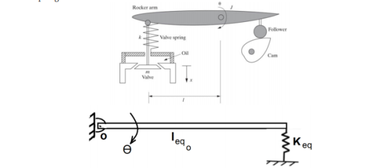
A rough sketch of a valve-and-rocker-arm system for an internal combustion engine is give in Figure shown . We want to model the system as a beam pined at one end and attached to a spring at another end as shown for ?, angular displacement of the rocker arm. Find Ieq and Keq and determine the equations of motion and calculate an expression for the natural frequency. Here J is the rotational inertia of the rocker arm about its pivot point, k is the stiffness of the valve spring, and m is the mass of the valve and stem. Ignore the mass of the spring.
Homework Answers

Add Answer to:
A rough sketch of a valve-and-rocker-arm system for an internal
combustion engine is give in Figure...
Consider the push rod rocker and valve of engine valve system shown in the Figure. The...
 Consider the push rod rocker and valve of engine valve system shown in the Figure. The mass moment of inertia of the rocker about its axis is I, the masses of valve and push rod are my and my respectively. The valve spring stiffness is K, and its mass is m. The push rod can be replaced by a spring of equivalent stiffness K. Obtain the equation of motion of the system considering the rocker and valve to be rigid...
This document consists of 04 printed pages [Turn over Question 1 (CLO 1, PLO 2, C3)...
 This document consists of 04 printed pages [Turn over Question 1 (CLO 1, PLO 2, C3) Calculate the total energy in a damped system with frequency 2 rad's and damping ratio ( = 0.01 with mass 10 kg for the case xo = 0.1 m and vp=0. [25] I Rocker arm Follower Valve spring Oil Question 2 (CLO 1, PLO 2, C3) A rough sketch of a valve-and-rocker arm system for an internal combustion engine is given in Figure OHT...
Exercises 1. (introduction) Sketch or plot the displacement of the mass in a mass-spring system for at least two per...
 Exercises 1. (introduction) Sketch or plot the displacement of the mass in a mass-spring system for at least two periods for the case when Wn-2rad/s, 괴,-1mm, and eto =-v/5mm/s. 2. (introduction) The approximation sin θ ะ θ is reasonable for θ < 10°. If a pendulum of length 0.5m, has an initial position of 0()0, what is the maximum value of the initial angular velocity that can be given to the pendulum without violating this smll angle approximation? 3. (harmonic...
The figure shown below represents a simplified model of a jet engine mounted to a wing...
 The figure shown below
represents a simplified model of a jet engine mounted to a wing
through a mechanism that acts as a spring of stiffness k and has a
mass ms. Assume the engine has a moment of inertia J and mass m and
that the rotation of the engine (i.e. the vectoring of the engine)
is related to the vertical displacement of the engine, x(t), by the
radius, ro (i.e. x=ro). Calculate the equation of motion, x(t) of...
The figure shown below
represents a simplified model of a jet engine mounted to a wing
through a mechanism that acts as a spring of stiffness k and has a
mass ms. Assume the engine has a moment of inertia J and mass m and
that the rotation of the engine (i.e. the vectoring of the engine)
is related to the vertical displacement of the engine, x(t), by the
radius, ro (i.e. x=ro). Calculate the equation of motion, x(t) of...
Q2 A rotational mechanical system is shown in Figure 2.1. T(t) is the external torque and...
 Q2 A rotational mechanical system is shown in Figure 2.1. T(t) is the external torque and is the input to the system. 01(t) is the angular displacement of inertia Ji and O2(t) is the angular displacement of inertia J2. C and C are friction coefficients and K, and K2 are spring constants. (a) Draw the free-body diagrams for J; and Jz. (7 marks) (b) Derive the equations of motion for the system shown in Figure 2.1. (8 marks) (c) Using...
. The system shown below consists of a homogeneous rigid rod with mass m, length l,...
 . The system shown below consists of a homogeneous rigid rod with mass m, length l, and mass center of gravity G where the mass moment of inertia of the rod about G is given by: Translational spring with stiffness k supports the rod at point B, and rotational damper c, İs connected to the rod at its pivot point A as shown.ft) is an external force applied to the rod. Derive the equation of motion of the single degree...
2. Consider the system shown in the figure below, comprised of the same motor, steel beam,...
 2. Consider the system shown in the figure below, comprised of the same motor, steel beam, steel cable and crate All assumptions and properties are the same with one exception; the cable is no longer considered as rigid Cable properties: length = 4 m, diameter = 0.007 m, E = 207 GPa, Calculate the equivalent stiffness of the cable, in units of N/m. (See table 4.1.1 in your textbook) Draw an equivalent system diagram where the beam and cable each...
Figure P4.56a shows a Houdaille damper, which is a device attached to an engine crankshaft to...
 Figure P4.56a shows a Houdaille damper, which is a device attached to an engine crankshaft to reduce vibrations. The damper has an inertia ld that is free to rotate within an enclosure filled with viscous fluid. The inertia I p is the inertia of the fan-belt pulley. Modeling the crankshaft as a torsional spring kT, the damper system can be modeled as shown in part (b) of the figure. Derive the equation of motion with the angular displacements ep and...
Figure Pl 1-12 shows an oil field pump mechanism. The head of the rocker arm is...
 Figure Pl 1-12 shows an oil field pump mechanism. The head of the rocker arm is shaped such that the lower end of a flexible cable attached to it will always be directly over the well head regardless of the position of the rocker arm 4. The pump rod, which connects to the pump in the well casing, is connected to the lower end of the cable. The force in the pump rod on the up stroke is 2970 lb...
Figure Q1 illustrates a simple pressure relief valve system, which consists of a rigid L-shaped beam,...
 Figure Q1 illustrates a simple pressure relief valve system, which consists of a rigid L-shaped beam, hinged at a point where the horizontal part of the beam has length 2L and the vertical part has length L. A spring of stiffness k is attached midway along the horizontal part of the beam, and a damper with damping coefficient c is attached to the vertical part of the beam, at a distance 0.75L from the hinge, O. The pressure relief valve...
 Consider the push rod rocker and valve of engine valve system shown in the Figure. The mass moment of inertia of the rocker about its axis is I, the masses of valve and push rod are my and my respectively. The valve spring stiffness is K, and its mass is m. The push rod can be replaced by a spring of equivalent stiffness K. Obtain the equation of motion of the system considering the rocker and valve to be rigid...
 This document consists of 04 printed pages [Turn over Question 1 (CLO 1, PLO 2, C3) Calculate the total energy in a damped system with frequency 2 rad's and damping ratio ( = 0.01 with mass 10 kg for the case xo = 0.1 m and vp=0. [25] I Rocker arm Follower Valve spring Oil Question 2 (CLO 1, PLO 2, C3) A rough sketch of a valve-and-rocker arm system for an internal combustion engine is given in Figure OHT...
 Exercises 1. (introduction) Sketch or plot the displacement of the mass in a mass-spring system for at least two periods for the case when Wn-2rad/s, 괴,-1mm, and eto =-v/5mm/s. 2. (introduction) The approximation sin θ ะ θ is reasonable for θ < 10°. If a pendulum of length 0.5m, has an initial position of 0()0, what is the maximum value of the initial angular velocity that can be given to the pendulum without violating this smll angle approximation? 3. (harmonic...
 The figure shown below
represents a simplified model of a jet engine mounted to a wing
through a mechanism that acts as a spring of stiffness k and has a
mass ms. Assume the engine has a moment of inertia J and mass m and
that the rotation of the engine (i.e. the vectoring of the engine)
is related to the vertical displacement of the engine, x(t), by the
radius, ro (i.e. x=ro). Calculate the equation of motion, x(t) of...
The figure shown below
represents a simplified model of a jet engine mounted to a wing
through a mechanism that acts as a spring of stiffness k and has a
mass ms. Assume the engine has a moment of inertia J and mass m and
that the rotation of the engine (i.e. the vectoring of the engine)
is related to the vertical displacement of the engine, x(t), by the
radius, ro (i.e. x=ro). Calculate the equation of motion, x(t) of...
 Q2 A rotational mechanical system is shown in Figure 2.1. T(t) is the external torque and is the input to the system. 01(t) is the angular displacement of inertia Ji and O2(t) is the angular displacement of inertia J2. C and C are friction coefficients and K, and K2 are spring constants. (a) Draw the free-body diagrams for J; and Jz. (7 marks) (b) Derive the equations of motion for the system shown in Figure 2.1. (8 marks) (c) Using...
 . The system shown below consists of a homogeneous rigid rod with mass m, length l, and mass center of gravity G where the mass moment of inertia of the rod about G is given by: Translational spring with stiffness k supports the rod at point B, and rotational damper c, İs connected to the rod at its pivot point A as shown.ft) is an external force applied to the rod. Derive the equation of motion of the single degree...
 2. Consider the system shown in the figure below, comprised of the same motor, steel beam, steel cable and crate All assumptions and properties are the same with one exception; the cable is no longer considered as rigid Cable properties: length = 4 m, diameter = 0.007 m, E = 207 GPa, Calculate the equivalent stiffness of the cable, in units of N/m. (See table 4.1.1 in your textbook) Draw an equivalent system diagram where the beam and cable each...
 Figure P4.56a shows a Houdaille damper, which is a device attached to an engine crankshaft to reduce vibrations. The damper has an inertia ld that is free to rotate within an enclosure filled with viscous fluid. The inertia I p is the inertia of the fan-belt pulley. Modeling the crankshaft as a torsional spring kT, the damper system can be modeled as shown in part (b) of the figure. Derive the equation of motion with the angular displacements ep and...
 Figure Pl 1-12 shows an oil field pump mechanism. The head of the rocker arm is shaped such that the lower end of a flexible cable attached to it will always be directly over the well head regardless of the position of the rocker arm 4. The pump rod, which connects to the pump in the well casing, is connected to the lower end of the cable. The force in the pump rod on the up stroke is 2970 lb...
 Figure Q1 illustrates a simple pressure relief valve system, which consists of a rigid L-shaped beam, hinged at a point where the horizontal part of the beam has length 2L and the vertical part has length L. A spring of stiffness k is attached midway along the horizontal part of the beam, and a damper with damping coefficient c is attached to the vertical part of the beam, at a distance 0.75L from the hinge, O. The pressure relief valve...
Most questions answered within 3 hours.
-
Where is the error in this code sequence?
String s1 = "Hello";
String s2 = "ello";...
asked 11 months ago -
Financial data for Joel de Paris, Inc., for last year
follow:
Joel de Paris, Inc.
Balance...
asked 11 months ago -
Consider this reaction:
Al2(SO4)3 (aq)+ BaCl3
(aq) Al2Cl6 (aq)- +
3BaSO4(s) . What is the...
asked 11 months ago -
Suppose that Savneet is considering increasing her
recent random sample from 20 car rentals to 40...
asked 11 months ago -
Trucks arrive at an unloading terminal at an average rate of 120
per hour.
Trucks arrive...
asked 11 months ago -
Why are methanol and ethanol completely soluble in water while
octanol is not very little soluble....
asked 11 months ago -
A facilities manager at a university reads in a research report
that the mean amount of...
asked 11 months ago -
When the CuSO4 is rehydrated by adding water to the anhydrous
compound, is this an endothermic...
asked 11 months ago -
A ray of sunlight is passing from diamond into crown glass; the
angle of incidence is...
asked 11 months ago -
A block of mass 0.249 kg is placed on top of a light, vertical
spring of...
asked 11 months ago -
how do the kidneys compensate in the presences of acidosis
a) trigger hyperventilate
b) reserve acid...
asked 11 months ago -
Question 501 pts
The rental rate of capital to the firm increases. Which of the
following...
asked 11 months ago