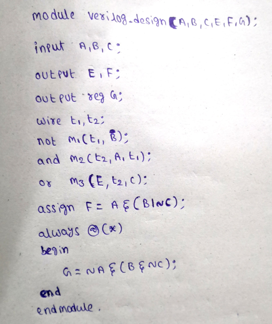
![[15 pts] Write a single Verilog module that will have three binary inputs, and have three binary outputs, 7) as described by](http://img.homeworklib.com/questions/bfa08c00-16a1-11ec-8c3a-2d2e2ce5ba4f.png?x-oss-process=image/resize,w_560)
Homework Answers
Add Answer to:
[15 pts] Write a single Verilog module that will have three binary inputs, and have three...
Write a behavioral Verilog module for a 4-bit Johnson counter that has 8 states. The counter load...
 Write a behavioral Verilog module for a 4-bit Johnson counter that has 8 states. The counter loads the "0000" state if reset is low. The counter should start and end with this state. Write a testbench to verify the correctness of the 4-bit Johnson counter. The testbenclh should have a clock with a period of 20ns and a reset signal. The testbench should store the 4-bit binary outputs of the counter in a file, which will be used to provide...
Write a Verilog program to implement and test a subtractor. The program should have three modules....
 Write a Verilog program to implement and test a subtractor. The program should have three modules. The first module, called cfulladder implements a one bit subtractor with two 1-bit outputs, S and Cout, and three one bit inputs A, B, Cin. You have to use always keyword to implement this combinational circuit. The second module, called sub4 implements a four bit subtractor by instantiating 4 cfulladder modules. It has the same inputs and outputs but now the S, A, and...
4) Finite State Machine (FSM) Write a System Verilog module using always_ff and always_comb that implements...
 4) Finite State Machine (FSM) Write a System Verilog module using always_ff and always_comb that implements the Finite machine in this state table. Use good code organization and indentation for full credit. State Transition Table State Assignment State Q3Q2Q1Q Present Next State State x-1 0001 0010 0100 1000 a) This state assignment indicates we are using what type of coding Which model of Finite State Machine is this, Mealy or Moore, Write the System Verilog code for the module statement...
[5 pts] Design a circuit with three inputs (x,y,z) and one output that outputs true if the binary value of the inputs i...
 [5 pts] Design a circuit with three inputs (x,y,z) and one output that outputs true if the binary value of the inputs is a perfect square (it's square root is an integer). Construct the truth table, simplify using a K-map, and draw out the logic circuit diagram
[5 pts] Design a circuit with three inputs (x,y,z) and one output that outputs true if the binary value of the inputs is a perfect square (it's square root is an integer). Construct...
[5 pts] Design a circuit with three inputs (x,y,z) and one output that outputs true if the binary value of the inputs is a perfect square (it's square root is an integer). Construct the truth table, simplify using a K-map, and draw out the logic circuit diagram
[5 pts] Design a circuit with three inputs (x,y,z) and one output that outputs true if the binary value of the inputs is a perfect square (it's square root is an integer). Construct...
(a) Write "continuous assign statement" in Verilog HDL for the output Z described by the below...
 (a) Write "continuous assign statement" in Verilog HDL for the output Z described by the below bread board setup. [Note that all the gates are NOR gates.) (8 points) V VCC GND GND O O VCC O (b) Write Verilog HDL for circuit in (a) using if-else statements within an always block. (6 points) (c) Write Verilog HDL for circuit in (a) using case statements within an always block. (6 points)
a) Write a verilog module for 1:4 Demultiplexer using verilog primitives. b) Design 1-to-4 DEMUX using...
a) Write a verilog module for 1:4 Demultiplexer using verilog primitives. b) Design 1-to-4 DEMUX using tristate buffers in verilog. c) Write a code in NIOS-II assembly to execute following statement: b=(a+b)-(c+d)
Design a combinational circuit with three inputs, x , y, and z, and three outputs, A,...
Design a combinational circuit with three inputs, x , y, and z, and three outputs, A, B , and C . When the binary input is 0, 1, 2, or 3, the binary output is one greater than the input. When the binary input is 4, 5, 6, or 7, the binary output is two less than the input. 1) Truth table 2) Logic circuit 3) Boolean function of A using minterms ( use Boolean algebra) 4) Boolean function of...
Acer Question Three Design a circuit with t wo inputs x & y representing the bits in a binary num...
 acer Question Three Design a circuit with t wo inputs x & y representing the bits in a binary number and outputs a& b also representing bits in a binary number. When t output is reversed. When the input is 1 and 3, the output s O and 2, the Any carry forward is discarded a) Show your truth table b) Find and simplify the Boolean expression for the o utputs a & b. c) Draw one logic circuit to...
1. Let's implement the traffic light controller from the previous assignment in Verilog, working with the following...
 1. Let's implement the traffic light controller from the previous assignment in Verilog, working with the following state and module interface definition: diagram car 0 car: 1 D/MR 1SY- car 0 C/MR-1,SG module trafficController (car, clock, MG,MY,MR,SG,SY,SR) input car,clock; output MG,MY,MR,SG,SY,SR; (a) Write a parameter definition for the state encodings. But let's define them as 1-hot encoded states rather than using fully encoded state values. (b) Define two reg variables to keep track of your current state and next state,...
number 4 and 5 please! PROBLEM STATEMENT A logic circuit is needed to add multi-bit binary...
 number 4 and 5 please!
PROBLEM STATEMENT A logic circuit is needed to add multi-bit binary numbers. A 2-level circuit that would add two four-bit numbers would have 9 inputs and five outputs. Although a 2-level SOP or POS circuit theoretically would be very fast, it has numerous drawbacks that make it impractical. The design would be very complex in terms of the number of logic gates. The number of inputs for each gate would challenge target technologies. Testing would...
number 4 and 5 please!
PROBLEM STATEMENT A logic circuit is needed to add multi-bit binary numbers. A 2-level circuit that would add two four-bit numbers would have 9 inputs and five outputs. Although a 2-level SOP or POS circuit theoretically would be very fast, it has numerous drawbacks that make it impractical. The design would be very complex in terms of the number of logic gates. The number of inputs for each gate would challenge target technologies. Testing would...
 Write a behavioral Verilog module for a 4-bit Johnson counter that has 8 states. The counter loads the "0000" state if reset is low. The counter should start and end with this state. Write a testbench to verify the correctness of the 4-bit Johnson counter. The testbenclh should have a clock with a period of 20ns and a reset signal. The testbench should store the 4-bit binary outputs of the counter in a file, which will be used to provide...
 Write a Verilog program to implement and test a subtractor. The program should have three modules. The first module, called cfulladder implements a one bit subtractor with two 1-bit outputs, S and Cout, and three one bit inputs A, B, Cin. You have to use always keyword to implement this combinational circuit. The second module, called sub4 implements a four bit subtractor by instantiating 4 cfulladder modules. It has the same inputs and outputs but now the S, A, and...
 4) Finite State Machine (FSM) Write a System Verilog module using always_ff and always_comb that implements the Finite machine in this state table. Use good code organization and indentation for full credit. State Transition Table State Assignment State Q3Q2Q1Q Present Next State State x-1 0001 0010 0100 1000 a) This state assignment indicates we are using what type of coding Which model of Finite State Machine is this, Mealy or Moore, Write the System Verilog code for the module statement...
 [5 pts] Design a circuit with three inputs (x,y,z) and one output that outputs true if the binary value of the inputs is a perfect square (it's square root is an integer). Construct the truth table, simplify using a K-map, and draw out the logic circuit diagram
[5 pts] Design a circuit with three inputs (x,y,z) and one output that outputs true if the binary value of the inputs is a perfect square (it's square root is an integer). Construct...
[5 pts] Design a circuit with three inputs (x,y,z) and one output that outputs true if the binary value of the inputs is a perfect square (it's square root is an integer). Construct the truth table, simplify using a K-map, and draw out the logic circuit diagram
[5 pts] Design a circuit with three inputs (x,y,z) and one output that outputs true if the binary value of the inputs is a perfect square (it's square root is an integer). Construct...
 (a) Write "continuous assign statement" in Verilog HDL for the output Z described by the below bread board setup. [Note that all the gates are NOR gates.) (8 points) V VCC GND GND O O VCC O (b) Write Verilog HDL for circuit in (a) using if-else statements within an always block. (6 points) (c) Write Verilog HDL for circuit in (a) using case statements within an always block. (6 points)
 acer Question Three Design a circuit with t wo inputs x & y representing the bits in a binary number and outputs a& b also representing bits in a binary number. When t output is reversed. When the input is 1 and 3, the output s O and 2, the Any carry forward is discarded a) Show your truth table b) Find and simplify the Boolean expression for the o utputs a & b. c) Draw one logic circuit to...
 1. Let's implement the traffic light controller from the previous assignment in Verilog, working with the following state and module interface definition: diagram car 0 car: 1 D/MR 1SY- car 0 C/MR-1,SG module trafficController (car, clock, MG,MY,MR,SG,SY,SR) input car,clock; output MG,MY,MR,SG,SY,SR; (a) Write a parameter definition for the state encodings. But let's define them as 1-hot encoded states rather than using fully encoded state values. (b) Define two reg variables to keep track of your current state and next state,...
 number 4 and 5 please!
PROBLEM STATEMENT A logic circuit is needed to add multi-bit binary numbers. A 2-level circuit that would add two four-bit numbers would have 9 inputs and five outputs. Although a 2-level SOP or POS circuit theoretically would be very fast, it has numerous drawbacks that make it impractical. The design would be very complex in terms of the number of logic gates. The number of inputs for each gate would challenge target technologies. Testing would...
number 4 and 5 please!
PROBLEM STATEMENT A logic circuit is needed to add multi-bit binary numbers. A 2-level circuit that would add two four-bit numbers would have 9 inputs and five outputs. Although a 2-level SOP or POS circuit theoretically would be very fast, it has numerous drawbacks that make it impractical. The design would be very complex in terms of the number of logic gates. The number of inputs for each gate would challenge target technologies. Testing would...
Most questions answered within 3 hours.
-
Where is the error in this code sequence?
String s1 = "Hello";
String s2 = "ello";...
asked 1 year ago -
Financial data for Joel de Paris, Inc., for last year
follow:
Joel de Paris, Inc.
Balance...
asked 1 year ago -
Consider this reaction:
Al2(SO4)3 (aq)+ BaCl3
(aq) Al2Cl6 (aq)- +
3BaSO4(s) . What is the...
asked 1 year ago -
Suppose that Savneet is considering increasing her
recent random sample from 20 car rentals to 40...
asked 1 year ago -
Trucks arrive at an unloading terminal at an average rate of 120
per hour.
Trucks arrive...
asked 1 year ago -
Why are methanol and ethanol completely soluble in water while
octanol is not very little soluble....
asked 1 year ago -
A facilities manager at a university reads in a research report
that the mean amount of...
asked 1 year ago -
When the CuSO4 is rehydrated by adding water to the anhydrous
compound, is this an endothermic...
asked 1 year ago -
A ray of sunlight is passing from diamond into crown glass; the
angle of incidence is...
asked 1 year ago -
A block of mass 0.249 kg is placed on top of a light, vertical
spring of...
asked 1 year ago -
how do the kidneys compensate in the presences of acidosis
a) trigger hyperventilate
b) reserve acid...
asked 1 year ago -
Question 501 pts
The rental rate of capital to the firm increases. Which of the
following...
asked 1 year ago