

Homework Answers


Add Answer to:
Need Immediate Help On Homework!
For the beam shown design #3 single loop stirrups. number of...
A reinforced concrete beam shown in Figure below is 15-in. wide and has effective depth of31 in. ...
 A reinforced concrete beam shown in Figure below is 15-in. wide and has effective depth of31 in. The factored loads are shown. (The factored uniform load includes the weight of the beam). Design the web reinforcement using the Vu diagram shown in the Figure (for a symmetric half). Assume No. 3 stirrups,fc '-4000 psi and fy=fyt-60000psi. 100 kip 100 kip d-31 in. 15 ft clear span As s) 102.5 kip se 2.5 ki @y、阪、もw cl.* 3..-K: ps
A reinforced concrete...
A reinforced concrete beam shown in Figure below is 15-in. wide and has effective depth of31 in. The factored loads are shown. (The factored uniform load includes the weight of the beam). Design the web reinforcement using the Vu diagram shown in the Figure (for a symmetric half). Assume No. 3 stirrups,fc '-4000 psi and fy=fyt-60000psi. 100 kip 100 kip d-31 in. 15 ft clear span As s) 102.5 kip se 2.5 ki @y、阪、もw cl.* 3..-K: ps
A reinforced concrete...
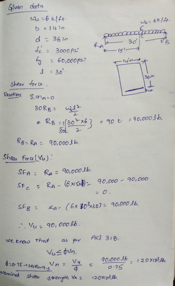
(40 pts) The simply supported beam shown in the figure below is being designed for shear. #3 stirrups (Grade 40) are to be used. 2. Wu = 4 kips/ft (includes self weight) wDL-1 kips/ft, wu...
 (40 pts) The simply supported beam shown in the figure below is being designed for shear. #3 stirrups (Grade 40) are to be used. 2. Wu = 4 kips/ft (includes self weight) wDL-1 kips/ft, wu 1.75 kips/ft h= 18" d = 15" L=20ft- fe-4000 psi Yoon- 150 lbf/t E-29,000 ksi fy60 ksi 2 IS Draw the factored shear envelope for Vu c. d. Determine the resistance to shear provided by the concrete. Are there any regions where no shear stirrups...
The T-beam shown in Figure 1 supports the un-factored dead load of 1.4 kips/ft and live...
 The T-beam shown in Figure 1 supports the un-factored dead load
of 1.4 kips/ft and live load of 1.5 kips/ft. The dead load does not
include the self-weight of the beam. The material properties are as
follows: fc’=3000 psi; fy=60,000 psi. Design the shear
reinforcement (stirrups). Plot the stirrups distribution along the
span of the beam.
DL= 1.4 kips/ft ; L2=1.5 kips/Ft * 75 Sz=7 X * b=3616. hr-6in k ) انا امه hw-lain + * bw=12 in
The T-beam shown in Figure 1 supports the un-factored dead load
of 1.4 kips/ft and live load of 1.5 kips/ft. The dead load does not
include the self-weight of the beam. The material properties are as
follows: fc’=3000 psi; fy=60,000 psi. Design the shear
reinforcement (stirrups). Plot the stirrups distribution along the
span of the beam.
DL= 1.4 kips/ft ; L2=1.5 kips/Ft * 75 Sz=7 X * b=3616. hr-6in k ) انا امه hw-lain + * bw=12 in
Need help with E and F please. 3. The beam shown in the figure below is...
 Need help with E and F please.
3. The beam shown in the figure below is carrying superimposed dead load of 25 kN/m and use and occupancy load of 45 kN/m. For preliminary analysis, assume a self weight of 10 kN/m. We are required to find the maximum positive (tension at the bottom) and negative (tension at the top) moments due to the factored loads, and then design the beam CIV E 374-RC-Lab 3 Fall 2018 (a) Determine the maximum...
Need help with E and F please.
3. The beam shown in the figure below is carrying superimposed dead load of 25 kN/m and use and occupancy load of 45 kN/m. For preliminary analysis, assume a self weight of 10 kN/m. We are required to find the maximum positive (tension at the bottom) and negative (tension at the top) moments due to the factored loads, and then design the beam CIV E 374-RC-Lab 3 Fall 2018 (a) Determine the maximum...
M 3: (20 points) Design the stirrup spacing for the beam shown below. Change your design between ...
 m 3: (20 points) Design the stirrup spacing for the beam shown below. Change your design between Zones 1, 2, and 3 of the beam length, using a uniform spacing in each zone. Ignore the self-weight of the beam. Loads on the beam are service loads so load factors must be applied according to ACI 318 (subscripts "d" and T" denote dead and live loads, respectively). Material strengths are fe 4,0oo psi and fy 60,000 psi. The total factored shear...
Please answer question 1 thank you Reinforced Concrete HW 18%20(2).pdf CEE433- Homework Assignment 9 Assigned: 12...
 Please answer question 1 thank you
Reinforced Concrete HW
18%20(2).pdf CEE433- Homework Assignment 9 Assigned: 12 April 2018 Due: 19 April 2018 1. Design the shear reinforcement (vertical stirrups) for the beam shown in the figure. Design stirrups based on the shear envelope using the approximate procedure discussed in class. Note that for the overhangs the maximum shear at the support is induced by placing dead and live loads throughout the cantilever portion. Satisfy all strength and spacing requirements specified...
Please answer question 1 thank you
Reinforced Concrete HW
18%20(2).pdf CEE433- Homework Assignment 9 Assigned: 12 April 2018 Due: 19 April 2018 1. Design the shear reinforcement (vertical stirrups) for the beam shown in the figure. Design stirrups based on the shear envelope using the approximate procedure discussed in class. Note that for the overhangs the maximum shear at the support is induced by placing dead and live loads throughout the cantilever portion. Satisfy all strength and spacing requirements specified...
Could you please help me on question 7. Thank you very much. The floor system shown...
 Could you please help me on question 7.
Thank you very much.
The floor system shown below consists of normalweight concrete (150 pcf). Beams C2 ! LT 1 7.0 inch ! h=20 in G2! 12 in Girders BI 1 7.0 inch Slab 8 ft span h 24 in ----- - -- - --- 15 in 15 ft 15 ft Use 4000 psi concrete and Gr. 60 reinforcing steel. Assume 0.75 inch clear cover. Include concrete self-weight and a superimposed dead...
Could you please help me on question 7.
Thank you very much.
The floor system shown below consists of normalweight concrete (150 pcf). Beams C2 ! LT 1 7.0 inch ! h=20 in G2! 12 in Girders BI 1 7.0 inch Slab 8 ft span h 24 in ----- - -- - --- 15 in 15 ft 15 ft Use 4000 psi concrete and Gr. 60 reinforcing steel. Assume 0.75 inch clear cover. Include concrete self-weight and a superimposed dead...
 A reinforced concrete beam shown in Figure below is 15-in. wide and has effective depth of31 in. The factored loads are shown. (The factored uniform load includes the weight of the beam). Design the web reinforcement using the Vu diagram shown in the Figure (for a symmetric half). Assume No. 3 stirrups,fc '-4000 psi and fy=fyt-60000psi. 100 kip 100 kip d-31 in. 15 ft clear span As s) 102.5 kip se 2.5 ki @y、阪、もw cl.* 3..-K: ps
A reinforced concrete...
A reinforced concrete beam shown in Figure below is 15-in. wide and has effective depth of31 in. The factored loads are shown. (The factored uniform load includes the weight of the beam). Design the web reinforcement using the Vu diagram shown in the Figure (for a symmetric half). Assume No. 3 stirrups,fc '-4000 psi and fy=fyt-60000psi. 100 kip 100 kip d-31 in. 15 ft clear span As s) 102.5 kip se 2.5 ki @y、阪、もw cl.* 3..-K: ps
A reinforced concrete...
 (40 pts) The simply supported beam shown in the figure below is being designed for shear. #3 stirrups (Grade 40) are to be used. 2. Wu = 4 kips/ft (includes self weight) wDL-1 kips/ft, wu 1.75 kips/ft h= 18" d = 15" L=20ft- fe-4000 psi Yoon- 150 lbf/t E-29,000 ksi fy60 ksi 2 IS Draw the factored shear envelope for Vu c. d. Determine the resistance to shear provided by the concrete. Are there any regions where no shear stirrups...
 The T-beam shown in Figure 1 supports the un-factored dead load
of 1.4 kips/ft and live load of 1.5 kips/ft. The dead load does not
include the self-weight of the beam. The material properties are as
follows: fc’=3000 psi; fy=60,000 psi. Design the shear
reinforcement (stirrups). Plot the stirrups distribution along the
span of the beam.
DL= 1.4 kips/ft ; L2=1.5 kips/Ft * 75 Sz=7 X * b=3616. hr-6in k ) انا امه hw-lain + * bw=12 in
The T-beam shown in Figure 1 supports the un-factored dead load
of 1.4 kips/ft and live load of 1.5 kips/ft. The dead load does not
include the self-weight of the beam. The material properties are as
follows: fc’=3000 psi; fy=60,000 psi. Design the shear
reinforcement (stirrups). Plot the stirrups distribution along the
span of the beam.
DL= 1.4 kips/ft ; L2=1.5 kips/Ft * 75 Sz=7 X * b=3616. hr-6in k ) انا امه hw-lain + * bw=12 in
 Need help with E and F please.
3. The beam shown in the figure below is carrying superimposed dead load of 25 kN/m and use and occupancy load of 45 kN/m. For preliminary analysis, assume a self weight of 10 kN/m. We are required to find the maximum positive (tension at the bottom) and negative (tension at the top) moments due to the factored loads, and then design the beam CIV E 374-RC-Lab 3 Fall 2018 (a) Determine the maximum...
Need help with E and F please.
3. The beam shown in the figure below is carrying superimposed dead load of 25 kN/m and use and occupancy load of 45 kN/m. For preliminary analysis, assume a self weight of 10 kN/m. We are required to find the maximum positive (tension at the bottom) and negative (tension at the top) moments due to the factored loads, and then design the beam CIV E 374-RC-Lab 3 Fall 2018 (a) Determine the maximum...
 m 3: (20 points) Design the stirrup spacing for the beam shown below. Change your design between Zones 1, 2, and 3 of the beam length, using a uniform spacing in each zone. Ignore the self-weight of the beam. Loads on the beam are service loads so load factors must be applied according to ACI 318 (subscripts "d" and T" denote dead and live loads, respectively). Material strengths are fe 4,0oo psi and fy 60,000 psi. The total factored shear...
 Please answer question 1 thank you
Reinforced Concrete HW
18%20(2).pdf CEE433- Homework Assignment 9 Assigned: 12 April 2018 Due: 19 April 2018 1. Design the shear reinforcement (vertical stirrups) for the beam shown in the figure. Design stirrups based on the shear envelope using the approximate procedure discussed in class. Note that for the overhangs the maximum shear at the support is induced by placing dead and live loads throughout the cantilever portion. Satisfy all strength and spacing requirements specified...
Please answer question 1 thank you
Reinforced Concrete HW
18%20(2).pdf CEE433- Homework Assignment 9 Assigned: 12 April 2018 Due: 19 April 2018 1. Design the shear reinforcement (vertical stirrups) for the beam shown in the figure. Design stirrups based on the shear envelope using the approximate procedure discussed in class. Note that for the overhangs the maximum shear at the support is induced by placing dead and live loads throughout the cantilever portion. Satisfy all strength and spacing requirements specified...
 Could you please help me on question 7.
Thank you very much.
The floor system shown below consists of normalweight concrete (150 pcf). Beams C2 ! LT 1 7.0 inch ! h=20 in G2! 12 in Girders BI 1 7.0 inch Slab 8 ft span h 24 in ----- - -- - --- 15 in 15 ft 15 ft Use 4000 psi concrete and Gr. 60 reinforcing steel. Assume 0.75 inch clear cover. Include concrete self-weight and a superimposed dead...
Could you please help me on question 7.
Thank you very much.
The floor system shown below consists of normalweight concrete (150 pcf). Beams C2 ! LT 1 7.0 inch ! h=20 in G2! 12 in Girders BI 1 7.0 inch Slab 8 ft span h 24 in ----- - -- - --- 15 in 15 ft 15 ft Use 4000 psi concrete and Gr. 60 reinforcing steel. Assume 0.75 inch clear cover. Include concrete self-weight and a superimposed dead...
Most questions answered within 3 hours.
-
Where is the error in this code sequence?
String s1 = "Hello";
String s2 = "ello";...
asked 10 months ago -
Financial data for Joel de Paris, Inc., for last year
follow:
Joel de Paris, Inc.
Balance...
asked 10 months ago -
Consider this reaction:
Al2(SO4)3 (aq)+ BaCl3
(aq) Al2Cl6 (aq)- +
3BaSO4(s) . What is the...
asked 10 months ago -
Suppose that Savneet is considering increasing her
recent random sample from 20 car rentals to 40...
asked 10 months ago -
Trucks arrive at an unloading terminal at an average rate of 120
per hour.
Trucks arrive...
asked 10 months ago -
Why are methanol and ethanol completely soluble in water while
octanol is not very little soluble....
asked 10 months ago -
A facilities manager at a university reads in a research report
that the mean amount of...
asked 10 months ago -
When the CuSO4 is rehydrated by adding water to the anhydrous
compound, is this an endothermic...
asked 10 months ago -
A ray of sunlight is passing from diamond into crown glass; the
angle of incidence is...
asked 10 months ago -
A block of mass 0.249 kg is placed on top of a light, vertical
spring of...
asked 10 months ago -
how do the kidneys compensate in the presences of acidosis
a) trigger hyperventilate
b) reserve acid...
asked 10 months ago -
Question 501 pts
The rental rate of capital to the firm increases. Which of the
following...
asked 10 months ago