A full subtractor can be built using two "Half Subtractor" devices and an OR gate. Design...
- A full subtractor can be built using two "Half
Subtractor" devices and an OR gate.
Design and test a full subtractor (schematic diagram and truth table shown below).
Write the expressions of the difference and the borrow beside the circuit.Input
Output
x
y
bi
bi+1
d
0
0
0
0
0
0
0
1
1
1
0
1
0
1
1
0
1
1
1
0
1
0
0
0
1
1
0
1
0
0
1
1
0
0
0
1
1
1
1
1
Hand-In
- The full subtractor circuit using two "Half Subtractor" devices and an OR gate
- Boolean functions for Difference and Borrow
- Show that a full subtractor can be implemented using a
"Full Adder" device and two inverter
gates.
For this, you will have to create a "Full Adder" device (Note: you can use the idea of what you built in question 2)
Build and test your circuit with the truth table.
Write the expressions of the difference and the borrow beside the circuit.Hand-In
- The underlying circuit of the "Full Adder " device. (Circuit with labeled ports--Part 1 in the notes)
- The testing circuit of the "Full Adder" device (the box) with binary switches and binary probes connected to it
- The full subtractor circuit using "Full Adder " device and two NOT gates
- Boolean functions for Difference and Borrow (a little different from question 5 because of the inverters)
Homework Answers


Add Answer to:
A full subtractor can be built using two "Half
Subtractor" devices and an OR gate.
Design...
5. A binary subtractor can be implemented using the carry look-ahead principle. (a) Draw the truth...
 5. A binary subtractor can be implemented using the carry look-ahead principle. (a) Draw the truth table of a binary subtractor. Use Xi, Yi, di, bi, and bi+1, for minuend, subtrahend, difference, borrow input, and borrow output respectively. (b) Derive expressions for the borrow-generate Yi and borrow propagate Ti signals for a binary subtractor. (c) Present the design of a circuit to compute d; and bi+1 from Yia Tį, and bi.
We know that the NAND gate is universal, so all other gates can be built using...
We know that the NAND gate is universal, so all other gates can be built using just NAND gates. Hence we should be able to build a half-adder using NAND gates. And we can. a) Draw the AND operation as a circuit using only 2 NAND gates b) Check your design in (a) by showing the full truth table for it c) Draw the OR operation as a circuit using only 3 NAND gates
We know that the NAND gate is universal, so all other gates can be built using...
We know that the NAND gate is universal, so all other gates can be built using just NAND gates. Hence we should be able to build a half-adder using NAND gates. And we can. a) Draw the AND operation as a circuit using only 2 NAND gates [2 marks] b) Check your design in (a) by showing the full truth table for it [2 marks] c) Draw the OR operation as a circuit using only 3 NAND gates [2 marks]...
3. PRELAB 1. A half adder is a circuit that has two inputs, A and B,...
 3. PRELAB 1. A half adder is a circuit that has two inputs, A and B, and two outputs, sum and carry. It adds A and B according to the rules of binary addition and outputs the sum and carry. Design a half-adder circuit using one XOR gate and one AND gate. Verify your design through truth table and with Multisim. 2. Whereas the half adder added two inputs A and B, the full adder adds three inputs together, A,...
Problem 5 (15%) Implement a full subtractor using only AND, OR. and NOT gates. A full...
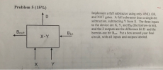 Problem 5 (15%) Implement a full subtractor using only AND, OR. and NOT gates. A full subtractor does a single-bit subtraction, subtracting Y from X. The three inputs to the device are X, Y, and Bin (the borrow-in bit), and the 2 outputs are the difference bit D and the borrow-out bit Bout. Put a box around your final circuit, with all inputs and outputs labeled. Bout x-y Bin
Building and testing basic combinational circuits using Verilog HDL Description: Build and test the following circuits using gate-level modeling in Verilog HDL 1.3-input majority function 2.Condition...
 Building and testing basic combinational circuits using Verilog HDL Description: Build and test the following circuits using gate-level modeling in Verilog HDL 1.3-input majority function 2.Conditional inverter (see the table below: x - control input, y -data input). Do NOT use XOR gates for the implementation. Output 3. Two-input multiplexer (see the table below: x.y -data inputs, z- control input) Output 4. 1-bit half adder. 5. 1-bit full adder by cascading two half adders 6.1-bit full adder directly (as in...
design a 1-bit full adder using a two level OR-AND circuit. Show truth tables, detail logic...
design a 1-bit full adder using a two level OR-AND circuit. Show truth tables, detail logic gate circuit design and boolean expression
Tim Question 1 Atte 20 pts 2H 24 Design a 1-bit Full Adder using NOR gates...
 Tim Question 1 Atte 20 pts 2H 24 Design a 1-bit Full Adder using NOR gates only, you must include and show: Truth tables, detail logic gate circuit designs, and Boolean expressions Upload Choose a File 20 pts Question 2 Design a 4-bit Full Adder with inputs (Xo...X3, Yo...Y3) in which inputs X are connect to two 4-bit registers via four 2-to-1 Multiplexers and inputs Y are connected to two other 4-bit registers via four 2-to-1 Multiplexers. In this case...
Verify that your design can be represented by the circuit below. 120 Full-Adder circuit Many of...
 Verify that your design can be represented by the circuit below. 120 Full-Adder circuit Many of the logic gates you require may not exist in standard TTL/CMOS 74 series family of logic. For example in future designs you may require a 50 input OR gate. The 74 series does not have a 50 input OR gate. For your 1 bit adder you will have the following devices: 1 quad 2 IP NAND, 1 TRIPLE 3 IP NAND, 7400 7410 7404...
Building and testing basic combinational circuits using Verilog HDL Description: Build and test t...
Building and testing basic combinational circuits using Verilog HDL Description: Build and test the following circuits using gate-level modeling in Verilog HDL. 1. 3-input majority function. 2. Conditional inverter (see the table below: x - control input, y - data input). Do NOT use XOR gates for the implementation. x y Output 0 y 1 y' 3. Two-input multiplexer (see the table below: x,y - data inputs, z - control input). z Output 0 x 1 y 4. 1-bit half...
 5. A binary subtractor can be implemented using the carry look-ahead principle. (a) Draw the truth table of a binary subtractor. Use Xi, Yi, di, bi, and bi+1, for minuend, subtrahend, difference, borrow input, and borrow output respectively. (b) Derive expressions for the borrow-generate Yi and borrow propagate Ti signals for a binary subtractor. (c) Present the design of a circuit to compute d; and bi+1 from Yia Tį, and bi.
 3. PRELAB 1. A half adder is a circuit that has two inputs, A and B, and two outputs, sum and carry. It adds A and B according to the rules of binary addition and outputs the sum and carry. Design a half-adder circuit using one XOR gate and one AND gate. Verify your design through truth table and with Multisim. 2. Whereas the half adder added two inputs A and B, the full adder adds three inputs together, A,...
 Problem 5 (15%) Implement a full subtractor using only AND, OR. and NOT gates. A full subtractor does a single-bit subtraction, subtracting Y from X. The three inputs to the device are X, Y, and Bin (the borrow-in bit), and the 2 outputs are the difference bit D and the borrow-out bit Bout. Put a box around your final circuit, with all inputs and outputs labeled. Bout x-y Bin
 Building and testing basic combinational circuits using Verilog HDL Description: Build and test the following circuits using gate-level modeling in Verilog HDL 1.3-input majority function 2.Conditional inverter (see the table below: x - control input, y -data input). Do NOT use XOR gates for the implementation. Output 3. Two-input multiplexer (see the table below: x.y -data inputs, z- control input) Output 4. 1-bit half adder. 5. 1-bit full adder by cascading two half adders 6.1-bit full adder directly (as in...
 Tim Question 1 Atte 20 pts 2H 24 Design a 1-bit Full Adder using NOR gates only, you must include and show: Truth tables, detail logic gate circuit designs, and Boolean expressions Upload Choose a File 20 pts Question 2 Design a 4-bit Full Adder with inputs (Xo...X3, Yo...Y3) in which inputs X are connect to two 4-bit registers via four 2-to-1 Multiplexers and inputs Y are connected to two other 4-bit registers via four 2-to-1 Multiplexers. In this case...
 Verify that your design can be represented by the circuit below. 120 Full-Adder circuit Many of the logic gates you require may not exist in standard TTL/CMOS 74 series family of logic. For example in future designs you may require a 50 input OR gate. The 74 series does not have a 50 input OR gate. For your 1 bit adder you will have the following devices: 1 quad 2 IP NAND, 1 TRIPLE 3 IP NAND, 7400 7410 7404...
Most questions answered within 3 hours.
-
Where is the error in this code sequence?
String s1 = "Hello";
String s2 = "ello";...
asked 11 months ago -
Financial data for Joel de Paris, Inc., for last year
follow:
Joel de Paris, Inc.
Balance...
asked 11 months ago -
Consider this reaction:
Al2(SO4)3 (aq)+ BaCl3
(aq) Al2Cl6 (aq)- +
3BaSO4(s) . What is the...
asked 11 months ago -
Suppose that Savneet is considering increasing her
recent random sample from 20 car rentals to 40...
asked 11 months ago -
Trucks arrive at an unloading terminal at an average rate of 120
per hour.
Trucks arrive...
asked 11 months ago -
Why are methanol and ethanol completely soluble in water while
octanol is not very little soluble....
asked 11 months ago -
A facilities manager at a university reads in a research report
that the mean amount of...
asked 11 months ago -
When the CuSO4 is rehydrated by adding water to the anhydrous
compound, is this an endothermic...
asked 11 months ago -
A ray of sunlight is passing from diamond into crown glass; the
angle of incidence is...
asked 11 months ago -
A block of mass 0.249 kg is placed on top of a light, vertical
spring of...
asked 11 months ago -
how do the kidneys compensate in the presences of acidosis
a) trigger hyperventilate
b) reserve acid...
asked 11 months ago -
Question 501 pts
The rental rate of capital to the firm increases. Which of the
following...
asked 11 months ago