Digital Circuits 1) Draw block diagrams to implement a 4 to 1 with 4 bits multiplexer. The data i...
Digital Circuits
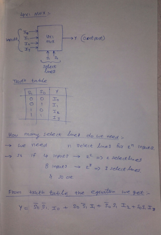
1) Draw block diagrams to implement a 4 to 1 with 4 bits multiplexer. The data input lines are 4 bits wide. Please decide how many selects do you need. And write the final equation for inputs and output in both your report and block diagram. Do the simulation.
Homework Answers

Add Answer to:
Digital Circuits 1) Draw block diagrams to implement a 4 to 1 with 4 bits multiplexer. The data i...
please draw a block diagram to implement the 1-4 with 4 bit demultiplexer and show the...
 please draw a block diagram to implement the 1-4 with
4 bit demultiplexer and show the simulation is possible
3. Please draw a block diagram to implement the 1-4 with 4-bit demultiplexer. 4. Draw a top-level diagram and then do the simulation. Data input F[3..0] Show the data F on the HEXO seven segment display; Select input Sel[1..0); Show the Select input value on the HEX1 seven segment display; Note: The number should be equal to one value from 0,1,2,3...
please draw a block diagram to implement the 1-4 with
4 bit demultiplexer and show the simulation is possible
3. Please draw a block diagram to implement the 1-4 with 4-bit demultiplexer. 4. Draw a top-level diagram and then do the simulation. Data input F[3..0] Show the data F on the HEXO seven segment display; Select input Sel[1..0); Show the Select input value on the HEX1 seven segment display; Note: The number should be equal to one value from 0,1,2,3...
Problem 1. Sequential Circuit Design Using a decoder and AND gates, implement a 4-input multiplexer. ....
 Problem 1. Sequential Circuit Design Using a decoder and AND gates, implement a 4-input multiplexer. . Using D-FFs, implement a 4-bit register. If using circuit verse, connect the Din signals to inputs blocks and connect Power to the enable lines. Do not forget the clock.
computer science question draw all the AND, OR, and NOT gates to implement a 4×1 multiplexer....
computer science question draw all the AND, OR, and NOT gates to implement a 4×1 multiplexer. Label all inputs and outputs appropriately.
Make a 4 bit 2 to 1 multiplexer circuit and block diagram and connect it to...
 Make a 4 bit 2 to 1 multiplexer circuit and block diagram and
connect it to a Hexadecimal-adder-subtractor. Ok so this is what
I've done, I already designed what's inside the mux block but I do
not know if this is the correct way to set up the connections
because it justs looks like a 4 to 1 multiplexer, but I do not know
if it is the same thing. Can you help me finish it and explain if
it...
Make a 4 bit 2 to 1 multiplexer circuit and block diagram and
connect it to a Hexadecimal-adder-subtractor. Ok so this is what
I've done, I already designed what's inside the mux block but I do
not know if this is the correct way to set up the connections
because it justs looks like a 4 to 1 multiplexer, but I do not know
if it is the same thing. Can you help me finish it and explain if
it...
digital logic design 4. (10 Points) Draw the output waveform for the following 4-input multiplexer with...
 digital logic design
4. (10 Points) Draw the output waveform for the following 4-input multiplexer with given input waveforms. S1 SO Y 0 0 IO MUN 0 1 11 SI SO 1 0 12 1 1 Si So 13 G Search or tune TIRI
digital logic design
4. (10 Points) Draw the output waveform for the following 4-input multiplexer with given input waveforms. S1 SO Y 0 0 IO MUN 0 1 11 SI SO 1 0 12 1 1 Si So 13 G Search or tune TIRI
Digital logic design Question 2 [4+6=10Marks] I. Implement following function using 16 x 1 multiplexer? F(A,B,C,D)...
 Digital logic design
Question 2 [4+6=10Marks] I. Implement following function using 16 x 1 multiplexer? F(A,B,C,D) = I l.ec.(D1, D2, D3, D4,10,11,13,15) II. Implement function F given above using 8 x 1 multiplexer?
Digital logic design
Question 2 [4+6=10Marks] I. Implement following function using 16 x 1 multiplexer? F(A,B,C,D) = I l.ec.(D1, D2, D3, D4,10,11,13,15) II. Implement function F given above using 8 x 1 multiplexer?
Can you use Multisim or something similar. I got the truth table and design, but having...
 Can you use Multisim or something similar. I got the truth table
and design, but having a hard time with the actual wiring.
I need to see where each cable and light bulb go.
3.4. Multiplexer Multiplexers are very useful components in digital systems. They transfer a large number of information units over a smaller number of channels, (usually one channel) under the control of selection signals. Fig. 3 is a 4-line to l-line MUX. In this circuit, lo, 11, 12,...
Can you use Multisim or something similar. I got the truth table
and design, but having a hard time with the actual wiring.
I need to see where each cable and light bulb go.
3.4. Multiplexer Multiplexers are very useful components in digital systems. They transfer a large number of information units over a smaller number of channels, (usually one channel) under the control of selection signals. Fig. 3 is a 4-line to l-line MUX. In this circuit, lo, 11, 12,...
please ansawer all thank you 1. Which of the following circuits are synchronous sequential circuits? Explain....
 please ansawer all thank you
1. Which of the following circuits are synchronous sequential circuits? Explain. CLK CLK CLK 2. Design an elevator controller for a building with 5 floors. This elevator only moves one floor at a time and only has inputs UP and DOWN. It produces an output indicating the floor the elevator is currently on. How many bits of state should you use? Draw the State Diagram only (do not write any Truth Tables).
please ansawer all thank you
1. Which of the following circuits are synchronous sequential circuits? Explain. CLK CLK CLK 2. Design an elevator controller for a building with 5 floors. This elevator only moves one floor at a time and only has inputs UP and DOWN. It produces an output indicating the floor the elevator is currently on. How many bits of state should you use? Draw the State Diagram only (do not write any Truth Tables).
Building and testing basic combinational circuits using Verilog HDL Description: Build and test t...
Building and testing basic combinational circuits using Verilog HDL Description: Build and test the following circuits using gate-level modeling in Verilog HDL. 1. 3-input majority function. 2. Conditional inverter (see the table below: x - control input, y - data input). Do NOT use XOR gates for the implementation. x y Output 0 y 1 y' 3. Two-input multiplexer (see the table below: x,y - data inputs, z - control input). z Output 0 x 1 y 4. 1-bit half...
Introduction Sequential logie circuits are circuits whose outputs depend not only on the present value of...
 Introduction Sequential logie circuits are circuits whose outputs depend not only on the present value of their input signals but also on the sequence of past inputs, the input history. Most sequential circuits we design are synchronous, or clocked. They use a rising or falling edge of a clock, or a level of an enable signal, to control their state or storage of data. For this project, you are required to design, implement, and test a PWM Generator, as well...
 please draw a block diagram to implement the 1-4 with
4 bit demultiplexer and show the simulation is possible
3. Please draw a block diagram to implement the 1-4 with 4-bit demultiplexer. 4. Draw a top-level diagram and then do the simulation. Data input F[3..0] Show the data F on the HEXO seven segment display; Select input Sel[1..0); Show the Select input value on the HEX1 seven segment display; Note: The number should be equal to one value from 0,1,2,3...
please draw a block diagram to implement the 1-4 with
4 bit demultiplexer and show the simulation is possible
3. Please draw a block diagram to implement the 1-4 with 4-bit demultiplexer. 4. Draw a top-level diagram and then do the simulation. Data input F[3..0] Show the data F on the HEXO seven segment display; Select input Sel[1..0); Show the Select input value on the HEX1 seven segment display; Note: The number should be equal to one value from 0,1,2,3...
 Problem 1. Sequential Circuit Design Using a decoder and AND gates, implement a 4-input multiplexer. . Using D-FFs, implement a 4-bit register. If using circuit verse, connect the Din signals to inputs blocks and connect Power to the enable lines. Do not forget the clock.
 Make a 4 bit 2 to 1 multiplexer circuit and block diagram and
connect it to a Hexadecimal-adder-subtractor. Ok so this is what
I've done, I already designed what's inside the mux block but I do
not know if this is the correct way to set up the connections
because it justs looks like a 4 to 1 multiplexer, but I do not know
if it is the same thing. Can you help me finish it and explain if
it...
Make a 4 bit 2 to 1 multiplexer circuit and block diagram and
connect it to a Hexadecimal-adder-subtractor. Ok so this is what
I've done, I already designed what's inside the mux block but I do
not know if this is the correct way to set up the connections
because it justs looks like a 4 to 1 multiplexer, but I do not know
if it is the same thing. Can you help me finish it and explain if
it...
 digital logic design
4. (10 Points) Draw the output waveform for the following 4-input multiplexer with given input waveforms. S1 SO Y 0 0 IO MUN 0 1 11 SI SO 1 0 12 1 1 Si So 13 G Search or tune TIRI
digital logic design
4. (10 Points) Draw the output waveform for the following 4-input multiplexer with given input waveforms. S1 SO Y 0 0 IO MUN 0 1 11 SI SO 1 0 12 1 1 Si So 13 G Search or tune TIRI
 Digital logic design
Question 2 [4+6=10Marks] I. Implement following function using 16 x 1 multiplexer? F(A,B,C,D) = I l.ec.(D1, D2, D3, D4,10,11,13,15) II. Implement function F given above using 8 x 1 multiplexer?
Digital logic design
Question 2 [4+6=10Marks] I. Implement following function using 16 x 1 multiplexer? F(A,B,C,D) = I l.ec.(D1, D2, D3, D4,10,11,13,15) II. Implement function F given above using 8 x 1 multiplexer?
 Can you use Multisim or something similar. I got the truth table
and design, but having a hard time with the actual wiring.
I need to see where each cable and light bulb go.
3.4. Multiplexer Multiplexers are very useful components in digital systems. They transfer a large number of information units over a smaller number of channels, (usually one channel) under the control of selection signals. Fig. 3 is a 4-line to l-line MUX. In this circuit, lo, 11, 12,...
Can you use Multisim or something similar. I got the truth table
and design, but having a hard time with the actual wiring.
I need to see where each cable and light bulb go.
3.4. Multiplexer Multiplexers are very useful components in digital systems. They transfer a large number of information units over a smaller number of channels, (usually one channel) under the control of selection signals. Fig. 3 is a 4-line to l-line MUX. In this circuit, lo, 11, 12,...
 please ansawer all thank you
1. Which of the following circuits are synchronous sequential circuits? Explain. CLK CLK CLK 2. Design an elevator controller for a building with 5 floors. This elevator only moves one floor at a time and only has inputs UP and DOWN. It produces an output indicating the floor the elevator is currently on. How many bits of state should you use? Draw the State Diagram only (do not write any Truth Tables).
please ansawer all thank you
1. Which of the following circuits are synchronous sequential circuits? Explain. CLK CLK CLK 2. Design an elevator controller for a building with 5 floors. This elevator only moves one floor at a time and only has inputs UP and DOWN. It produces an output indicating the floor the elevator is currently on. How many bits of state should you use? Draw the State Diagram only (do not write any Truth Tables).
 Introduction Sequential logie circuits are circuits whose outputs depend not only on the present value of their input signals but also on the sequence of past inputs, the input history. Most sequential circuits we design are synchronous, or clocked. They use a rising or falling edge of a clock, or a level of an enable signal, to control their state or storage of data. For this project, you are required to design, implement, and test a PWM Generator, as well...
Most questions answered within 3 hours.
-
Where is the error in this code sequence?
String s1 = "Hello";
String s2 = "ello";...
asked 11 months ago -
Financial data for Joel de Paris, Inc., for last year
follow:
Joel de Paris, Inc.
Balance...
asked 11 months ago -
Consider this reaction:
Al2(SO4)3 (aq)+ BaCl3
(aq) Al2Cl6 (aq)- +
3BaSO4(s) . What is the...
asked 11 months ago -
Suppose that Savneet is considering increasing her
recent random sample from 20 car rentals to 40...
asked 11 months ago -
Trucks arrive at an unloading terminal at an average rate of 120
per hour.
Trucks arrive...
asked 11 months ago -
Why are methanol and ethanol completely soluble in water while
octanol is not very little soluble....
asked 11 months ago -
A facilities manager at a university reads in a research report
that the mean amount of...
asked 11 months ago -
When the CuSO4 is rehydrated by adding water to the anhydrous
compound, is this an endothermic...
asked 11 months ago -
A ray of sunlight is passing from diamond into crown glass; the
angle of incidence is...
asked 11 months ago -
A block of mass 0.249 kg is placed on top of a light, vertical
spring of...
asked 11 months ago -
how do the kidneys compensate in the presences of acidosis
a) trigger hyperventilate
b) reserve acid...
asked 11 months ago -
Question 501 pts
The rental rate of capital to the firm increases. Which of the
following...
asked 11 months ago