
It is a question about Computer organization
Homework Answers


Add Answer to:
It is a question about Computer organization 1. Design a sequential counter that counts as follows: 1.1. Draw the st...
It is a question about Computer organization Design a sequential up/down counter. The counter should count...
 It is a question about Computer organization
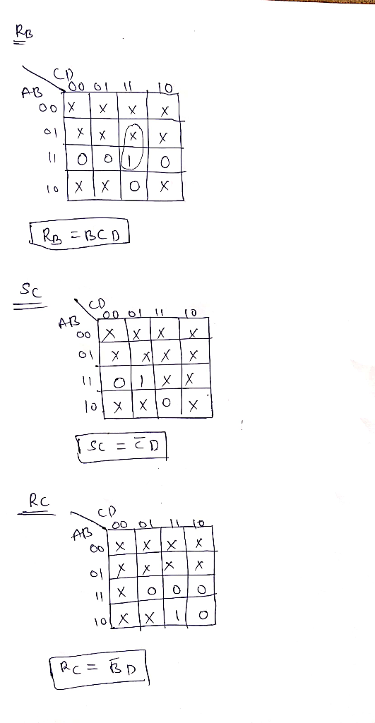
Design a sequential up/down counter. The counter should count as follows: When x -0, the counter will count 0, 1, 2, 3, 4, 5, 6, 7, 0,... When x 1, the counter will count 7, 6, 5, 4, 3, 2, 1, 0,7, .. 6.1. Draw the state diagram. 6.2. Draw the state table. 6. 6.3. Draw the excitation table using JK flip-flop. 6.4. Minimize. 6.5. Draw the logic diagram of your answer.
It is a question about Computer organization
Design a sequential up/down counter. The counter should count as follows: When x -0, the counter will count 0, 1, 2, 3, 4, 5, 6, 7, 0,... When x 1, the counter will count 7, 6, 5, 4, 3, 2, 1, 0,7, .. 6.1. Draw the state diagram. 6.2. Draw the state table. 6. 6.3. Draw the excitation table using JK flip-flop. 6.4. Minimize. 6.5. Draw the logic diagram of your answer.
Design an up/down counter with four states (0, 1, 2, 3) using clocked J-K flip-flops. A...
 Design an up/down counter with four states (0, 1, 2, 3) using clocked J-K flip-flops. A control signal x is used as follows: When x 0 the machine counts forward (up), when x , backward (down). Simulate using MultiSim and attach a simulation printout X Please address the following in your report 1. State Table 2. State Diagram 3. Flip-Flop Excitation Tables 4 K-Map Simplification and resulting diagram 5. Multisim Simulation 6. Conclusion/Discussion 7. References
Design an up/down counter with...
Design an up/down counter with four states (0, 1, 2, 3) using clocked J-K flip-flops. A control signal x is used as follows: When x 0 the machine counts forward (up), when x , backward (down). Simulate using MultiSim and attach a simulation printout X Please address the following in your report 1. State Table 2. State Diagram 3. Flip-Flop Excitation Tables 4 K-Map Simplification and resulting diagram 5. Multisim Simulation 6. Conclusion/Discussion 7. References
Design an up/down counter with...
Design a 3-bit down counter FSM with no inputs and three outputs. Do this using a...
Design a 3-bit down counter FSM with no inputs and three outputs. Do this using a T flip flop. a. Draw a state diagram and the corresponding state table. b. Derive the equations for output functions and flip-flop input functions c. Draw the logic circuit diagram
ercise 5 Part One: Sequential Logic ask 5.1,1: Design a 4-bit up/down counter that does not...
 ercise 5 Part One: Sequential Logic ask 5.1,1: Design a 4-bit up/down counter that does not overflow or underflow. That is, counting up is disabled when it reaches its maximum value and counting down is disabled when it reaches its minimum value. Use circuit simulation to verify your design. Task 5.1.2: Design a logic implementation of the Finite State Machine in Fiqure 2.3 using JK flip flops. It can be assumed that unused state combinations may be considered as don't...
Can you please help answer b) and c) ? Design a synchronous counter that counts through...
 Can you please help answer b)
and c) ?
Design a synchronous counter that counts through the following sequence using J-K flip flop. 7+9+1+3+8+0+5+4+6+2+10+12+11+1413 Step of programming: a) Build an Excitation Table b) Create an expression of the flip-flop c) Sketch the circuit based on expression
Can you please help answer b)
and c) ?
Design a synchronous counter that counts through the following sequence using J-K flip flop. 7+9+1+3+8+0+5+4+6+2+10+12+11+1413 Step of programming: a) Build an Excitation Table b) Create an expression of the flip-flop c) Sketch the circuit based on expression
answer a,b,c,d all of them one question 1 / 2 Question #2. Design of a Sequential...
 answer a,b,c,d all of them one question
1 / 2 Question #2. Design of a Sequential Circuit: A SEQUENCE DETECTOR that detects the sequence 11 must be designed whose present output z(k) is set to one when the past input (k-1) is one and the present input u(k) is also one, where for the other three possible combinations of the input pair u(k-1), uk) the present outputz(k) is set to zero. The state diagram for a sequential circuit that detects...
answer a,b,c,d all of them one question
1 / 2 Question #2. Design of a Sequential Circuit: A SEQUENCE DETECTOR that detects the sequence 11 must be designed whose present output z(k) is set to one when the past input (k-1) is one and the present input u(k) is also one, where for the other three possible combinations of the input pair u(k-1), uk) the present outputz(k) is set to zero. The state diagram for a sequential circuit that detects...
•Design a counter with repeated binary sequence 0,2,4,6,8 make thetable•From the table you made...
 •Design a counter with repeated binary sequence 0,2,4,6,8 make the
table•From the table you made find the expression for the flip flop
input.•Draw the Kamaugh map for the flip flop Da,Db,Dc,Dd•Draw the logic diagram for the required counter.Please use the picture provided and write neat and clear as
possible. Thank you
•Design a counter with repeated binary sequence 0,2,4,6,8 make the
table•From the table you made find the expression for the flip flop
input.•Draw the Kamaugh map for the flip flop Da,Db,Dc,Dd•Draw the logic diagram for the required counter.Please use the picture provided and write neat and clear as
possible. Thank you
Design a 5-bit binary counter using JK flip flops. Draw the flip-flop circuit diagram, the state...
Design a 5-bit binary counter using JK flip flops. Draw the flip-flop circuit diagram, the state graph, the timing diagram, the truth table (with clk pulse) and the state table (with present and next states).
task 1: In digital electronics and modern computer hardware, a flip-flop is sequential digital circuit used...
 task 1: In digital electronics and modern computer hardware, a flip-flop is sequential digital circuit used as a basic memory element. It has two stable states and can be used to store state information. One of its states represents '1' while the other represents '0'. The most common types of flip-flops are SR-flip-flop, JK-flip-flop, and D flip-flop. When used in a finite-state machine, the output and next state depend not only on its current input, but also on its current...
Design a synchronous counter that counts up 0, 1, 2, 3, 0, 1, 2, 3, ......
Design a synchronous counter that counts up 0, 1, 2, 3, 0, 1, 2, 3, ... when an input x = 1, and down when x = 0 using (a) D flip-flops. (b) J-K flip-flops. You need to show the state definition table, the state transition diagram, the state transition table, the K-maps for the respective logic functions and the schematic of the implementation using flipflops and logic gates in (a) as well as the K-maps for the logic functions...
 It is a question about Computer organization
Design a sequential up/down counter. The counter should count as follows: When x -0, the counter will count 0, 1, 2, 3, 4, 5, 6, 7, 0,... When x 1, the counter will count 7, 6, 5, 4, 3, 2, 1, 0,7, .. 6.1. Draw the state diagram. 6.2. Draw the state table. 6. 6.3. Draw the excitation table using JK flip-flop. 6.4. Minimize. 6.5. Draw the logic diagram of your answer.
It is a question about Computer organization
Design a sequential up/down counter. The counter should count as follows: When x -0, the counter will count 0, 1, 2, 3, 4, 5, 6, 7, 0,... When x 1, the counter will count 7, 6, 5, 4, 3, 2, 1, 0,7, .. 6.1. Draw the state diagram. 6.2. Draw the state table. 6. 6.3. Draw the excitation table using JK flip-flop. 6.4. Minimize. 6.5. Draw the logic diagram of your answer.
 Design an up/down counter with four states (0, 1, 2, 3) using clocked J-K flip-flops. A control signal x is used as follows: When x 0 the machine counts forward (up), when x , backward (down). Simulate using MultiSim and attach a simulation printout X Please address the following in your report 1. State Table 2. State Diagram 3. Flip-Flop Excitation Tables 4 K-Map Simplification and resulting diagram 5. Multisim Simulation 6. Conclusion/Discussion 7. References
Design an up/down counter with...
Design an up/down counter with four states (0, 1, 2, 3) using clocked J-K flip-flops. A control signal x is used as follows: When x 0 the machine counts forward (up), when x , backward (down). Simulate using MultiSim and attach a simulation printout X Please address the following in your report 1. State Table 2. State Diagram 3. Flip-Flop Excitation Tables 4 K-Map Simplification and resulting diagram 5. Multisim Simulation 6. Conclusion/Discussion 7. References
Design an up/down counter with...
 ercise 5 Part One: Sequential Logic ask 5.1,1: Design a 4-bit up/down counter that does not overflow or underflow. That is, counting up is disabled when it reaches its maximum value and counting down is disabled when it reaches its minimum value. Use circuit simulation to verify your design. Task 5.1.2: Design a logic implementation of the Finite State Machine in Fiqure 2.3 using JK flip flops. It can be assumed that unused state combinations may be considered as don't...
 Can you please help answer b)
and c) ?
Design a synchronous counter that counts through the following sequence using J-K flip flop. 7+9+1+3+8+0+5+4+6+2+10+12+11+1413 Step of programming: a) Build an Excitation Table b) Create an expression of the flip-flop c) Sketch the circuit based on expression
Can you please help answer b)
and c) ?
Design a synchronous counter that counts through the following sequence using J-K flip flop. 7+9+1+3+8+0+5+4+6+2+10+12+11+1413 Step of programming: a) Build an Excitation Table b) Create an expression of the flip-flop c) Sketch the circuit based on expression
 answer a,b,c,d all of them one question
1 / 2 Question #2. Design of a Sequential Circuit: A SEQUENCE DETECTOR that detects the sequence 11 must be designed whose present output z(k) is set to one when the past input (k-1) is one and the present input u(k) is also one, where for the other three possible combinations of the input pair u(k-1), uk) the present outputz(k) is set to zero. The state diagram for a sequential circuit that detects...
answer a,b,c,d all of them one question
1 / 2 Question #2. Design of a Sequential Circuit: A SEQUENCE DETECTOR that detects the sequence 11 must be designed whose present output z(k) is set to one when the past input (k-1) is one and the present input u(k) is also one, where for the other three possible combinations of the input pair u(k-1), uk) the present outputz(k) is set to zero. The state diagram for a sequential circuit that detects...
 •Design a counter with repeated binary sequence 0,2,4,6,8 make the
table•From the table you made find the expression for the flip flop
input.•Draw the Kamaugh map for the flip flop Da,Db,Dc,Dd•Draw the logic diagram for the required counter.Please use the picture provided and write neat and clear as
possible. Thank you
•Design a counter with repeated binary sequence 0,2,4,6,8 make the
table•From the table you made find the expression for the flip flop
input.•Draw the Kamaugh map for the flip flop Da,Db,Dc,Dd•Draw the logic diagram for the required counter.Please use the picture provided and write neat and clear as
possible. Thank you
 task 1: In digital electronics and modern computer hardware, a flip-flop is sequential digital circuit used as a basic memory element. It has two stable states and can be used to store state information. One of its states represents '1' while the other represents '0'. The most common types of flip-flops are SR-flip-flop, JK-flip-flop, and D flip-flop. When used in a finite-state machine, the output and next state depend not only on its current input, but also on its current...
Most questions answered within 3 hours.
-
Where is the error in this code sequence?
String s1 = "Hello";
String s2 = "ello";...
asked 11 months ago -
Financial data for Joel de Paris, Inc., for last year
follow:
Joel de Paris, Inc.
Balance...
asked 11 months ago -
Consider this reaction:
Al2(SO4)3 (aq)+ BaCl3
(aq) Al2Cl6 (aq)- +
3BaSO4(s) . What is the...
asked 11 months ago -
Suppose that Savneet is considering increasing her
recent random sample from 20 car rentals to 40...
asked 11 months ago -
Trucks arrive at an unloading terminal at an average rate of 120
per hour.
Trucks arrive...
asked 11 months ago -
Why are methanol and ethanol completely soluble in water while
octanol is not very little soluble....
asked 11 months ago -
A facilities manager at a university reads in a research report
that the mean amount of...
asked 11 months ago -
When the CuSO4 is rehydrated by adding water to the anhydrous
compound, is this an endothermic...
asked 11 months ago -
A ray of sunlight is passing from diamond into crown glass; the
angle of incidence is...
asked 11 months ago -
A block of mass 0.249 kg is placed on top of a light, vertical
spring of...
asked 11 months ago -
how do the kidneys compensate in the presences of acidosis
a) trigger hyperventilate
b) reserve acid...
asked 11 months ago -
Question 501 pts
The rental rate of capital to the firm increases. Which of the
following...
asked 11 months ago