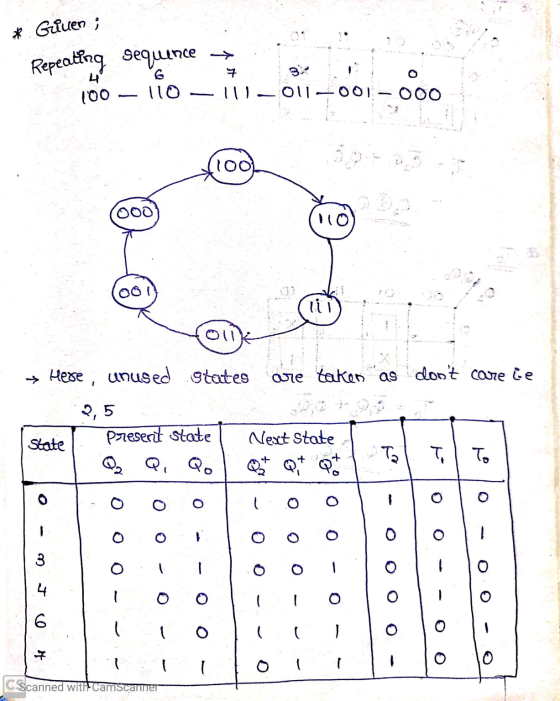
Design a Binary Counter with the repeating sequence of 100 - 110 - 111 - 011...

Homework Answers

Add Answer to:
Design a Binary Counter with the repeating sequence of 100 - 110 - 111 - 011...
Use D flip-flops to design a 3-bit counter
 Use D flip-flops to design a 3-bit counter which counts in the sequence: 110, 100,
101, 111, 011, 010, 001, (repeat) 110, . . .
In this case, what will happen if the counter is started in state 000?
Use D flip-flops to design a 3-bit counter which counts in the sequence: 110, 100,
101, 111, 011, 010, 001, (repeat) 110, . . .
In this case, what will happen if the counter is started in state 000?
Design a counter that counts in the sequence assigned to you. 000, 011, 101, 111, 010,...
Design a counter that counts in the sequence assigned to you. 000, 011, 101, 111, 010, 110, (repeat) 000, ... Use D flip-flops, NAND gates, and inverters. Draw your circuit explicitly showing all connections to gate and flip-flop inputs. Explicitly means that you should draw in all wires, don’t just label the inputs and outputs. Show switches connected to the Preset and Clear inputs of the flip-flops. Use one switch for all clears and a separate switch for each preset....
(4 pts) Write a behavioral Verilog module to implement a counter that counts in the following seq...
 Verilog! NOT VHDL Please
(4 pts) Write a behavioral Verilog module to implement a counter that counts in the following sequence: 000, 010, 100, 110, 001, 011, 101, 111, (repeat) 000, etc. Use a ROM and D flip-flops. Create a test bench for your counter design and run functional simulation in ModelSim.
(4 pts) Write a behavioral Verilog module to implement a counter that counts in the following sequence: 000, 010, 100, 110, 001, 011, 101, 111, (repeat) 000, etc....
Verilog! NOT VHDL Please
(4 pts) Write a behavioral Verilog module to implement a counter that counts in the following sequence: 000, 010, 100, 110, 001, 011, 101, 111, (repeat) 000, etc. Use a ROM and D flip-flops. Create a test bench for your counter design and run functional simulation in ModelSim.
(4 pts) Write a behavioral Verilog module to implement a counter that counts in the following sequence: 000, 010, 100, 110, 001, 011, 101, 111, (repeat) 000, etc....
Using S-R flip-flops, design a 3-bit counter (C,B,A) with the repeating binary counting sequence: 1, 3,...
Using S-R flip-flops, design a 3-bit counter (C,B,A) with the repeating binary counting sequence: 1, 3, 2, 6, 7, 5, 4. - Show the circuit's state table with the present-state entries in ascending order, which should have the present state (t), next state (t+1), and flip-flop inputs. - Find the flip-flop input equations for RC, RB, and RA in Product of Sums form.
Design a synchronous counter that has the following sequence: 000, 010, 101, 110 and repeat. The...
Design a synchronous counter that has the following sequence: 000, 010, 101, 110 and repeat. The undesired states 001, 011, 100 and 111 must always go to 000 on the next clock pulse.
14. Design a cyclic counter that produces the binary sequence 0, 2, 3,1. o..if the control signal...
 14?
14. Design a cyclic counter that produces the binary sequence 0, 2, 3,1. o..if the control signal X is 0 but produces the binary sequence 0, 1,3,2.0, if the control signal X is1.Use D flip-flops. (a) Draw the state diagram; (6 points (b) Draw the input, present state-next state, excitation table: (6 points) (c) Derive the minimal SOP expressions for the D inputs of the flip-flops using K-maps. Draw the logic circuit realization of the counter, using only NAND...
14?
14. Design a cyclic counter that produces the binary sequence 0, 2, 3,1. o..if the control signal X is 0 but produces the binary sequence 0, 1,3,2.0, if the control signal X is1.Use D flip-flops. (a) Draw the state diagram; (6 points (b) Draw the input, present state-next state, excitation table: (6 points) (c) Derive the minimal SOP expressions for the D inputs of the flip-flops using K-maps. Draw the logic circuit realization of the counter, using only NAND...
Design a 3 bits binary counter that count up from 000 to 111 and recycles according to the following specification: E i...
 Design a 3 bits binary counter that count up from 000 to 111 and recycles according to the following specification: E is the enable input, if E-0 the counter is disabled and remains in its current state even though clock pulses are applied to the flip-flops. And if E-1 the counter is enabled and count upward with the sequence 000,001,010,011,100,101,110, 111 The second input S is the reset if s-1 the counter is reset to the 000 state, is S-o...
C. The task is to create a complex counter that can count in binary or in...
 C. The task is to create a complex counter that can count in binary or in Gray code, depending on the value of a mode input: "A synchronous 3-bit counter has a mode control input m. When m = 0, the counter steps through the binary sequence 000, 001,010, 011, 100, 101, 110, 111, and repeat. When m = 1, the counter advances through the Gray code sequence 000, 001,011, 010, 110, 111, 101, 100, and repeat. (USE JK FLIP...
using J-K flip-flops, design a synchronous counter to produce the following repeating sequence 0,6,2,4,0 and prove it in Multisim.
using J-K flip-flops, design a synchronous counter to produce the following repeating sequence 0,6,2,4,0 and prove it in Multisim.
Design a Verilog model that describes the following state diagram. (Test bench and simulation are not required) 1. 01 10 1- 10 10 01 01 10 or 01) 01 Design a Verilog model that describes a synchr...
 Design a Verilog model that describes the following state diagram. (Test bench and simulation are not required) 1. 01 10 1- 10 10 01 01 10 or 01) 01 Design a Verilog model that describes a synchronous 3 bit counter. The counter has a counting mode control signal (M), when M-o, the counter counts up in the binary sequence, when M- 1, the counter advances through the Gray code sequence. (Test bench and simulation are required to verify the counter...
 Verilog! NOT VHDL Please
(4 pts) Write a behavioral Verilog module to implement a counter that counts in the following sequence: 000, 010, 100, 110, 001, 011, 101, 111, (repeat) 000, etc. Use a ROM and D flip-flops. Create a test bench for your counter design and run functional simulation in ModelSim.
(4 pts) Write a behavioral Verilog module to implement a counter that counts in the following sequence: 000, 010, 100, 110, 001, 011, 101, 111, (repeat) 000, etc....
Verilog! NOT VHDL Please
(4 pts) Write a behavioral Verilog module to implement a counter that counts in the following sequence: 000, 010, 100, 110, 001, 011, 101, 111, (repeat) 000, etc. Use a ROM and D flip-flops. Create a test bench for your counter design and run functional simulation in ModelSim.
(4 pts) Write a behavioral Verilog module to implement a counter that counts in the following sequence: 000, 010, 100, 110, 001, 011, 101, 111, (repeat) 000, etc....
 14?
14. Design a cyclic counter that produces the binary sequence 0, 2, 3,1. o..if the control signal X is 0 but produces the binary sequence 0, 1,3,2.0, if the control signal X is1.Use D flip-flops. (a) Draw the state diagram; (6 points (b) Draw the input, present state-next state, excitation table: (6 points) (c) Derive the minimal SOP expressions for the D inputs of the flip-flops using K-maps. Draw the logic circuit realization of the counter, using only NAND...
14?
14. Design a cyclic counter that produces the binary sequence 0, 2, 3,1. o..if the control signal X is 0 but produces the binary sequence 0, 1,3,2.0, if the control signal X is1.Use D flip-flops. (a) Draw the state diagram; (6 points (b) Draw the input, present state-next state, excitation table: (6 points) (c) Derive the minimal SOP expressions for the D inputs of the flip-flops using K-maps. Draw the logic circuit realization of the counter, using only NAND...
 Design a 3 bits binary counter that count up from 000 to 111 and recycles according to the following specification: E is the enable input, if E-0 the counter is disabled and remains in its current state even though clock pulses are applied to the flip-flops. And if E-1 the counter is enabled and count upward with the sequence 000,001,010,011,100,101,110, 111 The second input S is the reset if s-1 the counter is reset to the 000 state, is S-o...
 C. The task is to create a complex counter that can count in binary or in Gray code, depending on the value of a mode input: "A synchronous 3-bit counter has a mode control input m. When m = 0, the counter steps through the binary sequence 000, 001,010, 011, 100, 101, 110, 111, and repeat. When m = 1, the counter advances through the Gray code sequence 000, 001,011, 010, 110, 111, 101, 100, and repeat. (USE JK FLIP...
 Design a Verilog model that describes the following state diagram. (Test bench and simulation are not required) 1. 01 10 1- 10 10 01 01 10 or 01) 01 Design a Verilog model that describes a synchronous 3 bit counter. The counter has a counting mode control signal (M), when M-o, the counter counts up in the binary sequence, when M- 1, the counter advances through the Gray code sequence. (Test bench and simulation are required to verify the counter...
Most questions answered within 3 hours.
-
Where is the error in this code sequence?
String s1 = "Hello";
String s2 = "ello";...
asked 11 months ago -
Financial data for Joel de Paris, Inc., for last year
follow:
Joel de Paris, Inc.
Balance...
asked 11 months ago -
Consider this reaction:
Al2(SO4)3 (aq)+ BaCl3
(aq) Al2Cl6 (aq)- +
3BaSO4(s) . What is the...
asked 11 months ago -
Suppose that Savneet is considering increasing her
recent random sample from 20 car rentals to 40...
asked 11 months ago -
Trucks arrive at an unloading terminal at an average rate of 120
per hour.
Trucks arrive...
asked 11 months ago -
Why are methanol and ethanol completely soluble in water while
octanol is not very little soluble....
asked 11 months ago -
A facilities manager at a university reads in a research report
that the mean amount of...
asked 11 months ago -
When the CuSO4 is rehydrated by adding water to the anhydrous
compound, is this an endothermic...
asked 11 months ago -
A ray of sunlight is passing from diamond into crown glass; the
angle of incidence is...
asked 11 months ago -
A block of mass 0.249 kg is placed on top of a light, vertical
spring of...
asked 11 months ago -
how do the kidneys compensate in the presences of acidosis
a) trigger hyperventilate
b) reserve acid...
asked 11 months ago -
Question 501 pts
The rental rate of capital to the firm increases. Which of the
following...
asked 11 months ago