
Homework Answers
Add Answer to:
C. The task is to create a complex counter that can count in binary or in...
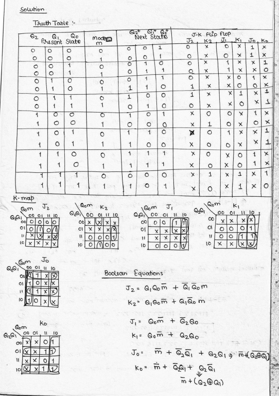
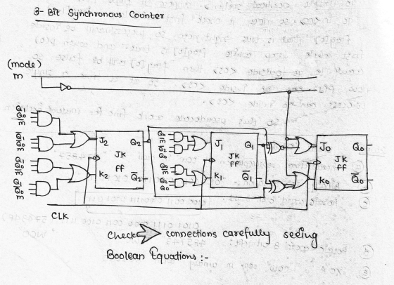
Design a Verilog model that describes the following state diagram. (Test bench and simulation are not required) 1. 01 10 1- 10 10 01 01 10 or 01) 01 Design a Verilog model that describes a synchr...
 Design a Verilog model that describes the following state diagram. (Test bench and simulation are not required) 1. 01 10 1- 10 10 01 01 10 or 01) 01 Design a Verilog model that describes a synchronous 3 bit counter. The counter has a counting mode control signal (M), when M-o, the counter counts up in the binary sequence, when M- 1, the counter advances through the Gray code sequence. (Test bench and simulation are required to verify the counter...
will give thumbs up need answer asap P3.94pts Implement a 3-bit synchronous gray code down-counter with...
 will give thumbs up need answer asap
P3.94pts Implement a 3-bit synchronous gray code down-counter with positive-edge-triggered D flip-flops using graphical symbols of D flip-flops and any logic gates. You can refer to the table below to understand the 3-bit gray code (The desired behavior is as follows: 000 100 101 111 - 110 - 010011001 → 000 → ...). Decimal 1 Gray code 000 001 011 010 110 111 101 100 5 6
will give thumbs up need answer asap
P3.94pts Implement a 3-bit synchronous gray code down-counter with positive-edge-triggered D flip-flops using graphical symbols of D flip-flops and any logic gates. You can refer to the table below to understand the 3-bit gray code (The desired behavior is as follows: 000 100 101 111 - 110 - 010011001 → 000 → ...). Decimal 1 Gray code 000 001 011 010 110 111 101 100 5 6
Use D flip-flops to design a 3-bit counter
 Use D flip-flops to design a 3-bit counter which counts in the sequence: 110, 100,
101, 111, 011, 010, 001, (repeat) 110, . . .
In this case, what will happen if the counter is started in state 000?
Use D flip-flops to design a 3-bit counter which counts in the sequence: 110, 100,
101, 111, 011, 010, 001, (repeat) 110, . . .
In this case, what will happen if the counter is started in state 000?
verilog code needed for the counter using the JK flip flop please include the testbench, thanks!...
 verilog code needed for the counter using the JK flip
flop
please include the testbench, thanks!
Successfully completing a System Verilog +80Pts. Implementation showing the full sequence of ABC readouts Pre-Laboratory Exercise: You are to design a counter that will count through a sequence either forward or reverse. You will have two control inputs: Direction, and Reset'. Sequence #2: 000 100 110 111 101001 → 011 010 → 000... {Gray code} When Direction=0 follow the order listed above. When Direction...
verilog code needed for the counter using the JK flip
flop
please include the testbench, thanks!
Successfully completing a System Verilog +80Pts. Implementation showing the full sequence of ABC readouts Pre-Laboratory Exercise: You are to design a counter that will count through a sequence either forward or reverse. You will have two control inputs: Direction, and Reset'. Sequence #2: 000 100 110 111 101001 → 011 010 → 000... {Gray code} When Direction=0 follow the order listed above. When Direction...
The first eight elements of binary and Gray code are given below: Binary | Gray 000...
The first eight elements of binary and Gray code are given below: Binary | Gray 000 | 000 001 | 001 010 | 011 011 | 010 100 | 110 101 | 111 110 | 101 111 | 100 Design a circuit that converts from binary to Gray code.
(4 pts) Write a behavioral Verilog module to implement a counter that counts in the following seq...
 Verilog! NOT VHDL Please
(4 pts) Write a behavioral Verilog module to implement a counter that counts in the following sequence: 000, 010, 100, 110, 001, 011, 101, 111, (repeat) 000, etc. Use a ROM and D flip-flops. Create a test bench for your counter design and run functional simulation in ModelSim.
(4 pts) Write a behavioral Verilog module to implement a counter that counts in the following sequence: 000, 010, 100, 110, 001, 011, 101, 111, (repeat) 000, etc....
Verilog! NOT VHDL Please
(4 pts) Write a behavioral Verilog module to implement a counter that counts in the following sequence: 000, 010, 100, 110, 001, 011, 101, 111, (repeat) 000, etc. Use a ROM and D flip-flops. Create a test bench for your counter design and run functional simulation in ModelSim.
(4 pts) Write a behavioral Verilog module to implement a counter that counts in the following sequence: 000, 010, 100, 110, 001, 011, 101, 111, (repeat) 000, etc....
Design a synchronous counter that has the following sequence: 000, 010, 101, 110 and repeat. The...
Design a synchronous counter that has the following sequence: 000, 010, 101, 110 and repeat. The undesired states 001, 011, 100 and 111 must always go to 000 on the next clock pulse.
Question 4 State Machines (25 marks) a. (5 marks) A 3-bit Gray code counter advances on...
 Question 4 State Machines (25 marks) a. (5 marks) A 3-bit Gray code counter advances on positive clock edges and generates outputs in the sequence: 000, 001, 011, 010, 110, 111, 101, 100. Draw the assigned state table for a state machine implementing this counter. b. (10 marks) For the Gray code counter in part a, derive (unoptimised) equations for the next state as a function of the current state. c. (10 marks) Consider the following sequence detector. In each...
Finite state machine (FSM) counter design: Gray codes have a useful property in that consecutive numbers differ in only a single bit position. Table 1 lists a 3-bit modulo 8 Gray code representing the...
 Finite state machine (FSM) counter design: Gray
codes have a useful property in that consecutive numbers differ in
only a single bit position. Table 1 lists a 3-bit modulo 8 Gray
code representing the numbers 0 to 7. Design a 3-bit modulo 8 Gray
code counter FSM.
a) First design and sketch a 3-bit modulo 8 Gray code counter
FSM with no inputs and three outputs, the 3-bit signal
Q2:0. (A modulo N counter counts from 0 to N −...
Finite state machine (FSM) counter design: Gray
codes have a useful property in that consecutive numbers differ in
only a single bit position. Table 1 lists a 3-bit modulo 8 Gray
code representing the numbers 0 to 7. Design a 3-bit modulo 8 Gray
code counter FSM.
a) First design and sketch a 3-bit modulo 8 Gray code counter
FSM with no inputs and three outputs, the 3-bit signal
Q2:0. (A modulo N counter counts from 0 to N −...
Design a Binary Counter with the repeating sequence of 100 - 110 - 111 - 011...
 Design a Binary Counter with the repeating sequence of 100 - 110 - 111 - 011 - 001 - 000 using T Flip-Flops. Find the input expressions of the T Flip-Flops by K-Map.
 Design a Verilog model that describes the following state diagram. (Test bench and simulation are not required) 1. 01 10 1- 10 10 01 01 10 or 01) 01 Design a Verilog model that describes a synchronous 3 bit counter. The counter has a counting mode control signal (M), when M-o, the counter counts up in the binary sequence, when M- 1, the counter advances through the Gray code sequence. (Test bench and simulation are required to verify the counter...
 will give thumbs up need answer asap
P3.94pts Implement a 3-bit synchronous gray code down-counter with positive-edge-triggered D flip-flops using graphical symbols of D flip-flops and any logic gates. You can refer to the table below to understand the 3-bit gray code (The desired behavior is as follows: 000 100 101 111 - 110 - 010011001 → 000 → ...). Decimal 1 Gray code 000 001 011 010 110 111 101 100 5 6
will give thumbs up need answer asap
P3.94pts Implement a 3-bit synchronous gray code down-counter with positive-edge-triggered D flip-flops using graphical symbols of D flip-flops and any logic gates. You can refer to the table below to understand the 3-bit gray code (The desired behavior is as follows: 000 100 101 111 - 110 - 010011001 → 000 → ...). Decimal 1 Gray code 000 001 011 010 110 111 101 100 5 6
 verilog code needed for the counter using the JK flip
flop
please include the testbench, thanks!
Successfully completing a System Verilog +80Pts. Implementation showing the full sequence of ABC readouts Pre-Laboratory Exercise: You are to design a counter that will count through a sequence either forward or reverse. You will have two control inputs: Direction, and Reset'. Sequence #2: 000 100 110 111 101001 → 011 010 → 000... {Gray code} When Direction=0 follow the order listed above. When Direction...
verilog code needed for the counter using the JK flip
flop
please include the testbench, thanks!
Successfully completing a System Verilog +80Pts. Implementation showing the full sequence of ABC readouts Pre-Laboratory Exercise: You are to design a counter that will count through a sequence either forward or reverse. You will have two control inputs: Direction, and Reset'. Sequence #2: 000 100 110 111 101001 → 011 010 → 000... {Gray code} When Direction=0 follow the order listed above. When Direction...
 Verilog! NOT VHDL Please
(4 pts) Write a behavioral Verilog module to implement a counter that counts in the following sequence: 000, 010, 100, 110, 001, 011, 101, 111, (repeat) 000, etc. Use a ROM and D flip-flops. Create a test bench for your counter design and run functional simulation in ModelSim.
(4 pts) Write a behavioral Verilog module to implement a counter that counts in the following sequence: 000, 010, 100, 110, 001, 011, 101, 111, (repeat) 000, etc....
Verilog! NOT VHDL Please
(4 pts) Write a behavioral Verilog module to implement a counter that counts in the following sequence: 000, 010, 100, 110, 001, 011, 101, 111, (repeat) 000, etc. Use a ROM and D flip-flops. Create a test bench for your counter design and run functional simulation in ModelSim.
(4 pts) Write a behavioral Verilog module to implement a counter that counts in the following sequence: 000, 010, 100, 110, 001, 011, 101, 111, (repeat) 000, etc....
 Question 4 State Machines (25 marks) a. (5 marks) A 3-bit Gray code counter advances on positive clock edges and generates outputs in the sequence: 000, 001, 011, 010, 110, 111, 101, 100. Draw the assigned state table for a state machine implementing this counter. b. (10 marks) For the Gray code counter in part a, derive (unoptimised) equations for the next state as a function of the current state. c. (10 marks) Consider the following sequence detector. In each...
 Finite state machine (FSM) counter design: Gray
codes have a useful property in that consecutive numbers differ in
only a single bit position. Table 1 lists a 3-bit modulo 8 Gray
code representing the numbers 0 to 7. Design a 3-bit modulo 8 Gray
code counter FSM.
a) First design and sketch a 3-bit modulo 8 Gray code counter
FSM with no inputs and three outputs, the 3-bit signal
Q2:0. (A modulo N counter counts from 0 to N −...
Finite state machine (FSM) counter design: Gray
codes have a useful property in that consecutive numbers differ in
only a single bit position. Table 1 lists a 3-bit modulo 8 Gray
code representing the numbers 0 to 7. Design a 3-bit modulo 8 Gray
code counter FSM.
a) First design and sketch a 3-bit modulo 8 Gray code counter
FSM with no inputs and three outputs, the 3-bit signal
Q2:0. (A modulo N counter counts from 0 to N −...
 Design a Binary Counter with the repeating sequence of 100 - 110 - 111 - 011 - 001 - 000 using T Flip-Flops. Find the input expressions of the T Flip-Flops by K-Map.
Most questions answered within 3 hours.
-
Where is the error in this code sequence?
String s1 = "Hello";
String s2 = "ello";...
asked 11 months ago -
Financial data for Joel de Paris, Inc., for last year
follow:
Joel de Paris, Inc.
Balance...
asked 11 months ago -
Consider this reaction:
Al2(SO4)3 (aq)+ BaCl3
(aq) Al2Cl6 (aq)- +
3BaSO4(s) . What is the...
asked 11 months ago -
Suppose that Savneet is considering increasing her
recent random sample from 20 car rentals to 40...
asked 11 months ago -
Trucks arrive at an unloading terminal at an average rate of 120
per hour.
Trucks arrive...
asked 11 months ago -
Why are methanol and ethanol completely soluble in water while
octanol is not very little soluble....
asked 11 months ago -
A facilities manager at a university reads in a research report
that the mean amount of...
asked 11 months ago -
When the CuSO4 is rehydrated by adding water to the anhydrous
compound, is this an endothermic...
asked 11 months ago -
A ray of sunlight is passing from diamond into crown glass; the
angle of incidence is...
asked 11 months ago -
A block of mass 0.249 kg is placed on top of a light, vertical
spring of...
asked 11 months ago -
how do the kidneys compensate in the presences of acidosis
a) trigger hyperventilate
b) reserve acid...
asked 11 months ago -
Question 501 pts
The rental rate of capital to the firm increases. Which of the
following...
asked 11 months ago