Find the equivalent capacitance of the group of capacitors shown in the figure below. (Let C1...
Find the equivalent capacitance of the group of capacitors shown in the figure below. (Let C1 = 4.60 µF, C2 = 3.80 µF, C3 = 3.10 µF, C4 = 2.20 µF, C5 = 2.70 µF, C6 = 7.20 µF, C7 = 6.10 µF.) A circuit is made up of two rectangular loops, one on top of the other. The bottom side of the lower loop contains a 48.0 V battery, where its positive terminal is to the left of its negative terminal. The top side of the lower loop, which is also the bottom side of the upper loop, contains a capacitor C7, then splits into three parallel horizontal branches before recombining and continuing to the end of the side. Each branch contains one capacitor. From top to bottom, they are C4, C5, and C6. The top side of the top loop splits into two parallel horizontal branches before recombining and continuing to a capacitor C3. Each branch contains one capacitor. From top to bottom, they are C1 and C2. µF
Homework Answers

Circuit Diagram.
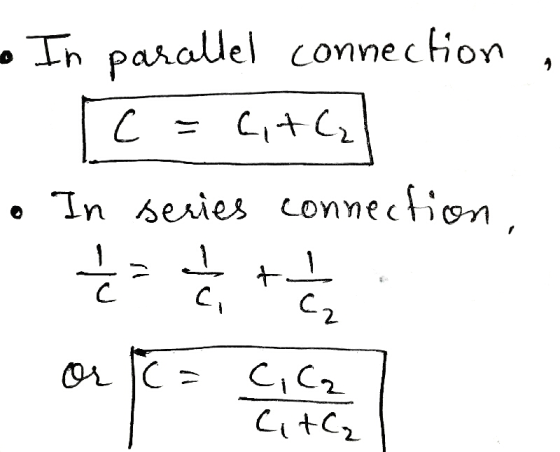
 calculating capacitance of
capacitors connected in parallel.
calculating capacitance of
capacitors connected in parallel.

Add Answer to:
Find the equivalent capacitance of the group of capacitors shown
in the figure below. (Let C1...
For the system of four capacitors shown in the figure below, find the following. (Use C1...
For the system of four capacitors shown in the figure below, find the following. (Use C1 = 4.00 µF, C2 = 1.00 µF, C3 = 5.00 µF, and C4 = 3.00 µF for the figure.) A circuit consists of a 90.0 V battery and four capacitors. The wire begins at the positive terminal of the battery and splits into two parallel branches before reconnecting and then ending at the negative terminal of the battery. Each branch contains two capacitors in...
Find the equivalent capacitance of the group of capacitors shown in the figure below. (Let C1...
 Find the equivalent capacitance of the group of capacitors shown
in the figure below. (Let C1 = 4.90 μF, C2 =
4.20 μF, C3 = 2.80 μF, C4 = 1.90 μF,
C5 = 2.80 μF, C6 = 7.50 μF, C7 =
5.70 μF.)
PLEASE ANSWER CORRECTLY. THANK YOU IN ADVANCE!!!
Safari File Edit View History Bookmarks Window Help 50% D' El Mon 3:08:36 PM a Submit Answer Save Progress Practice Another Version 2. 0/10 points I Previous Answers sercp11 16.a.p.065.nva...
Find the equivalent capacitance of the group of capacitors shown
in the figure below. (Let C1 = 4.90 μF, C2 =
4.20 μF, C3 = 2.80 μF, C4 = 1.90 μF,
C5 = 2.80 μF, C6 = 7.50 μF, C7 =
5.70 μF.)
PLEASE ANSWER CORRECTLY. THANK YOU IN ADVANCE!!!
Safari File Edit View History Bookmarks Window Help 50% D' El Mon 3:08:36 PM a Submit Answer Save Progress Practice Another Version 2. 0/10 points I Previous Answers sercp11 16.a.p.065.nva...
Consider the following. (Let C1 = 20.80 µF and C2 = 14.80 µF.) A rectangular circuit...
Consider the following. (Let C1 = 20.80 µF and C2 = 14.80 µF.) A rectangular circuit contains a battery and four capacitors. The bottom side has a 9.00 V battery with the positive terminal on the left. The left and right sides of the circuit each contain a capacitor labeled C1. The top side splits into two parallel horizontal branches, which recombine before reaching the top right corner. There is a 6.00 µF capacitor on the upper branch and a...
Consider the following. (Let C1 = 36.40 µF and C2 = 30.40 µF.) A rectangular circuit...
Consider the following. (Let C1 = 36.40 µF and C2 = 30.40 µF.) A rectangular circuit contains a battery and four capacitors. The bottom side has a 9.00 V battery with the positive terminal on the left. The left and right sides of the circuit each contain a capacitor labeled C1. The top side splits into two parallel horizontal branches, which recombine before reaching the top right corner. There is a 6.00 µF capacitor on the upper branch and a...
The circuit in the figure below contains a 90.0 V battery and four capacitors. In the...
The circuit in the figure below contains a 90.0 V battery and four capacitors. In the top parallel branch, there are two capacitors, one with a capacitance of C1 = 3.00 µF and another with a capacitance of 6.00 µF. In the bottom parallel branch, there are two more capacitors, one with a capacitance of 2.00 µF and another with a capacitance of C2 = 6.00 µF. A circuit consists of a 90.0 V battery and four capacitors. The wire...
Find the charge on each of the capacitors in the figure below. A rectangular circuit contains...
 Find the charge on each of the capacitors in the figure below. A
rectangular circuit contains a battery and four capacitors. A 24.0
V battery is on its left side, where the positive terminal is above
the negative terminal. Its right side splits into two parallel
vertical branches below the top right corner of the circuit, where
there is a 1.00 µF capacitor on the left branch and a 5.00 µF
capacitor on the right branch. The branches recombine, the...
Find the charge on each of the capacitors in the figure below. A
rectangular circuit contains a battery and four capacitors. A 24.0
V battery is on its left side, where the positive terminal is above
the negative terminal. Its right side splits into two parallel
vertical branches below the top right corner of the circuit, where
there is a 1.00 µF capacitor on the left branch and a 5.00 µF
capacitor on the right branch. The branches recombine, the...
Answer the questions using the circuit shown a) Capacitor C1 is in -select- (parallel, series, or neither)...
 Answer the questions using the
circuit shown
a) Capacitor C1 is in -select-
(parallel, series, or neither) with capacitor
C2.
(b) Capacitor C4 is in -select-
(series, neither, or parallel) with capacitor
C6.
(c) Capacitor C1 is in -select-
(series, parallel, or neither) with capacitor
C6.
(d) Capacitor C3 is in -select-
(parallel, series, or neither) with capacitor
C5.
(e) Capacitor C4 is in -select-
(parallel neither, or series) with capacitor
C5.
(f) Capacitor C4 has the same voltage
difference as (Select all that apply.)...
Answer the questions using the
circuit shown
a) Capacitor C1 is in -select-
(parallel, series, or neither) with capacitor
C2.
(b) Capacitor C4 is in -select-
(series, neither, or parallel) with capacitor
C6.
(c) Capacitor C1 is in -select-
(series, parallel, or neither) with capacitor
C6.
(d) Capacitor C3 is in -select-
(parallel, series, or neither) with capacitor
C5.
(e) Capacitor C4 is in -select-
(parallel neither, or series) with capacitor
C5.
(f) Capacitor C4 has the same voltage
difference as (Select all that apply.)...
Find the total capacitance C tot of the combination of capacitors shown in the figure, where...
Find the total capacitance C tot of the combination of capacitors shown in the figure, where C 1 = 5.15 μF , C 2 = 3.55 μF , C 3 = 7.75 μF , C 4 = 1.25 μF , C 5 = 0.750 μF , and C 6 = 15.0 μF . A complex circuit containing 6 capacitors. The lead wire at the top of the diagram splits into three parallel branches that recombine at the bottom of the...
Find the total capacitance ? tot Ctot of the combination of capacitors shown in the figure,...
Find the total capacitance ? tot Ctot of the combination of capacitors shown in the figure, where ? 1 =5.15 μF C1=5.15 μF , ? 2 =3.55 μF C2=3.55 μF , ? 3 =8.25 μF C3=8.25 μF , ? 4 =1.75 μF C4=1.75 μF , ? 5 =0.750 μF C5=0.750 μF , and ? 6 =15.0 μF C6=15.0 μF .
Question9 Consider the circuit shown in the figure below. Calculate the voltage across the capacitor Co...
 Question9 Consider the circuit shown in the figure below. Calculate the voltage across the capacitor Co potential source and capacitor values: o12.0 V assuming the following Note this one is quite challenging and will be graded as extra credit C1 C Home netism Paddock [W19) C1 C2 C3 Vo C4 C5 C6 8 9
 Find the equivalent capacitance of the group of capacitors shown
in the figure below. (Let C1 = 4.90 μF, C2 =
4.20 μF, C3 = 2.80 μF, C4 = 1.90 μF,
C5 = 2.80 μF, C6 = 7.50 μF, C7 =
5.70 μF.)
PLEASE ANSWER CORRECTLY. THANK YOU IN ADVANCE!!!
Safari File Edit View History Bookmarks Window Help 50% D' El Mon 3:08:36 PM a Submit Answer Save Progress Practice Another Version 2. 0/10 points I Previous Answers sercp11 16.a.p.065.nva...
Find the equivalent capacitance of the group of capacitors shown
in the figure below. (Let C1 = 4.90 μF, C2 =
4.20 μF, C3 = 2.80 μF, C4 = 1.90 μF,
C5 = 2.80 μF, C6 = 7.50 μF, C7 =
5.70 μF.)
PLEASE ANSWER CORRECTLY. THANK YOU IN ADVANCE!!!
Safari File Edit View History Bookmarks Window Help 50% D' El Mon 3:08:36 PM a Submit Answer Save Progress Practice Another Version 2. 0/10 points I Previous Answers sercp11 16.a.p.065.nva...
 Find the charge on each of the capacitors in the figure below. A
rectangular circuit contains a battery and four capacitors. A 24.0
V battery is on its left side, where the positive terminal is above
the negative terminal. Its right side splits into two parallel
vertical branches below the top right corner of the circuit, where
there is a 1.00 µF capacitor on the left branch and a 5.00 µF
capacitor on the right branch. The branches recombine, the...
Find the charge on each of the capacitors in the figure below. A
rectangular circuit contains a battery and four capacitors. A 24.0
V battery is on its left side, where the positive terminal is above
the negative terminal. Its right side splits into two parallel
vertical branches below the top right corner of the circuit, where
there is a 1.00 µF capacitor on the left branch and a 5.00 µF
capacitor on the right branch. The branches recombine, the...
 Answer the questions using the
circuit shown
a) Capacitor C1 is in -select-
(parallel, series, or neither) with capacitor
C2.
(b) Capacitor C4 is in -select-
(series, neither, or parallel) with capacitor
C6.
(c) Capacitor C1 is in -select-
(series, parallel, or neither) with capacitor
C6.
(d) Capacitor C3 is in -select-
(parallel, series, or neither) with capacitor
C5.
(e) Capacitor C4 is in -select-
(parallel neither, or series) with capacitor
C5.
(f) Capacitor C4 has the same voltage
difference as (Select all that apply.)...
Answer the questions using the
circuit shown
a) Capacitor C1 is in -select-
(parallel, series, or neither) with capacitor
C2.
(b) Capacitor C4 is in -select-
(series, neither, or parallel) with capacitor
C6.
(c) Capacitor C1 is in -select-
(series, parallel, or neither) with capacitor
C6.
(d) Capacitor C3 is in -select-
(parallel, series, or neither) with capacitor
C5.
(e) Capacitor C4 is in -select-
(parallel neither, or series) with capacitor
C5.
(f) Capacitor C4 has the same voltage
difference as (Select all that apply.)...
 Question9 Consider the circuit shown in the figure below. Calculate the voltage across the capacitor Co potential source and capacitor values: o12.0 V assuming the following Note this one is quite challenging and will be graded as extra credit C1 C Home netism Paddock [W19) C1 C2 C3 Vo C4 C5 C6 8 9
Most questions answered within 3 hours.
-
Where is the error in this code sequence?
String s1 = "Hello";
String s2 = "ello";...
asked 10 months ago -
Financial data for Joel de Paris, Inc., for last year
follow:
Joel de Paris, Inc.
Balance...
asked 10 months ago -
Consider this reaction:
Al2(SO4)3 (aq)+ BaCl3
(aq) Al2Cl6 (aq)- +
3BaSO4(s) . What is the...
asked 10 months ago -
Suppose that Savneet is considering increasing her
recent random sample from 20 car rentals to 40...
asked 10 months ago -
Trucks arrive at an unloading terminal at an average rate of 120
per hour.
Trucks arrive...
asked 10 months ago -
Why are methanol and ethanol completely soluble in water while
octanol is not very little soluble....
asked 10 months ago -
A facilities manager at a university reads in a research report
that the mean amount of...
asked 10 months ago -
When the CuSO4 is rehydrated by adding water to the anhydrous
compound, is this an endothermic...
asked 10 months ago -
A ray of sunlight is passing from diamond into crown glass; the
angle of incidence is...
asked 10 months ago -
A block of mass 0.249 kg is placed on top of a light, vertical
spring of...
asked 10 months ago -
how do the kidneys compensate in the presences of acidosis
a) trigger hyperventilate
b) reserve acid...
asked 10 months ago -
Question 501 pts
The rental rate of capital to the firm increases. Which of the
following...
asked 10 months ago