Write a test bench to thoroughly test the Verilog module dff_fe_asyn_h. below is the module ddff_fe_asyn_h.code...
- Write a test bench to thoroughly test the Verilog module dff_fe_asyn_h. below is the module ddff_fe_asyn_h.code
- Simulate the circuit using ISim and analyze the resulting waveform.
- Take full screenshots of all Verilog source codes and the resulting simulation waveform to be included in the lab report. Include explanation of the waveform and how you can conclude that the D flip flop implemented in step 9 is correct in the lab report.
Verilog Code for dff_fe_asyn_h is mentioned below:-
//DFF module with asynchronous active high reset with negative
edge trigger with clock
module dff_fe_asyn_h (
input clock, // Clock Input
input reset, // Reset Input
input data_in, // Input Data
output reg data_out // Output Data
);
always @ (negedge clock or posedge reset) // triggers at the
negative edge of the clock
begin
if (reset) // Asynchronous Active High reset
data_out <= 1'b0;
else
data_out <= data_in; // When reset is not present then it
forward the input data to output
end
endmodule
Homework Answers
Solution :-
Part 1) :- Verilog design code
module dff_fe_asyn_h (
input clock, // Clock Input
input reset, // Reset Input
input data_in, // Input Data
output reg data_out // Output Data
);
always @ (negedge clock or posedge reset) // triggers at the
negative edge of the clock
begin
if (reset) // Asynchronous Active High reset
data_out <= 1'b0;
else
data_out <= data_in; // When reset is not present then it
forward the input data to output
end
endmodule
Tesbench code
`timescale 1ns / 1ps
module test_bench;
// Inputs
reg clock;
reg reset;
reg data_in;
// Outputs
wire data_out;
// Instantiate the Unit Under Test (UUT)
dff_fe_asyn_h uut (
.clock(clock),
.reset(reset),
.data_in(data_in),
.data_out(data_out)
);
always
#5 clock = !clock;
initial begin
// Initialize Inputs
clock = 1'b1;
reset = 1'b1;
data_in = 1'b0;
#20;
reset = 1'b0;
#40;
data_in = 1'b1;
#40;
reset = 1'b1;
#20;
reset = 1'b0;
data_in = 1'b0;
#30;
$finish;
end
endmodule
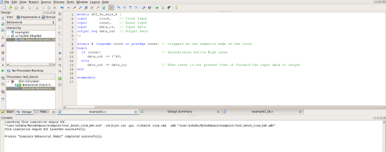
Snapshot for the Isim tool:-
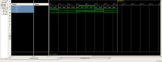
Waveform of the testbench:-
Add Answer to:
Write a test bench to thoroughly test the Verilog module
dff_fe_asyn_h. below is the module
ddff_fe_asyn_h.code...
Write a test bench to thoroughly test the Verilog module dff_fe_asyn_h. below is the module ddff_fe_asyn_h.code...
Write a test bench to thoroughly test the Verilog module dff_fe_asyn_h. below is the module ddff_fe_asyn_h.code Simulate the circuit using ISim and analyze the resulting waveform. Verilog Code for dff_fe_asyn_h is mentioned below:- //DFF module with asynchronous active high reset with negative edge trigger with clock module dff_fe_asyn_h ( input clock, // Clock Input input reset, // Reset Input input data_in, // Input Data output reg data_out // Output Data ); always @ (negedge clock or posedge reset) // triggers...
Write the verilog code that implements a negitive edge D-Flip Flop with asynchronous active low preset...
Write the verilog code that implements a negitive edge D-Flip Flop with asynchronous active low preset and clear I have : module dff( preset, clear, clk, D, Q) input preset; input clear; input clk; input D; output Q; reg Q; always @ (negedge clk or negedge preset or negedge clear); if (preset); Q = 0; else (clear == 0); Q = D; endmodule I honestly just want to know if i'm doing this right or not, if im not correct,...
Can anyone solve this? i dont understand? verilog 1. (30 pts) Design a mod-6 counter. A...
 Can anyone solve this? i dont understand? verilog
1. (30 pts) Design a mod-6 counter. A mod-6 counter updates its output per clock rising edge according to the following sequence: 000, 001, 010, 011, 100, 101 (then repeat the pattern....). en is enable control (synchronous high active), resetn is reset control (asynchronous low active signal to reset counting sequence to 000) Complete the following Verilog code: en module mod6(clock, resetn, en, z); zI2:0] clock resetn Endmodule
Can anyone solve this? i dont understand? verilog
1. (30 pts) Design a mod-6 counter. A mod-6 counter updates its output per clock rising edge according to the following sequence: 000, 001, 010, 011, 100, 101 (then repeat the pattern....). en is enable control (synchronous high active), resetn is reset control (asynchronous low active signal to reset counting sequence to 000) Complete the following Verilog code: en module mod6(clock, resetn, en, z); zI2:0] clock resetn Endmodule
10.21 Write a behavioral Verilog module vrDnegEc for a negative-edge-triggered D flip-flop with enable and asynchronous...
 10.21 Write a behavioral Verilog module vrDnegEc for a negative-edge-triggered D flip-flop with enable and asynchronous active-low clear. Also write a test bench that instantiates your flip-flop and exercises its operation for a comprehensive input sequence.
1. Write a Verilog module called myNot to implement the logic NOT gate. 2. Write a...
 1. Write a Verilog module called myNot to implement the logic NOT gate. 2. Write a test bench to test the myNot module created in step 10. Simulate the circuit using Sim and analyze the resulting waveform. 3. Take full screenshots of the source code of myNot module, the test bench Verilog file, and resulting simulation waveforms to be included in the lab report. Also include your waveform analysis in the lab report.
VERILOG CODE Design a new Verilog module to define a 4-bit counter algorithmically using behavioral modeling....
VERILOG CODE Design a new Verilog module to define a 4-bit counter algorithmically using behavioral modeling. This time we no longer need T FlipFlop submodule. The 4-bit counter can be directly implemented using a 4-bit register variable and adding 1 to its value as follows: input Clock, Clear, Enable; output reg [3:0] Q; always @ (posedge Clock or negedge Clear) if (~Clear) Q <= 0; else if (Enable) Q <= Q + 1'b1;
Use the Quartus Prime Text Editor to implement a behavioral model of the D flip-flop described ab...
 Use the Quartus Prime Text Editor to implement a behavioral
model of the D flip-flop described above in a file named
d_flops.sv. Specify the D flip-flop’s module according to the
interface specification given in the table below.
Port
Mode
Data Type
Size
Description
RST
in
logic
1-bit
Active high asynchronous reset
CLK
in
logic
1-bit
Synchronizing clock signal
EN
in
logic
1-bit
Synchronous clock enable
D
in
logic
1-bit
Synchronous data input
Q
out
logic
1-bit
Current/present state
Qbar
out...
Use the Quartus Prime Text Editor to implement a behavioral
model of the D flip-flop described above in a file named
d_flops.sv. Specify the D flip-flop’s module according to the
interface specification given in the table below.
Port
Mode
Data Type
Size
Description
RST
in
logic
1-bit
Active high asynchronous reset
CLK
in
logic
1-bit
Synchronizing clock signal
EN
in
logic
1-bit
Synchronous clock enable
D
in
logic
1-bit
Synchronous data input
Q
out
logic
1-bit
Current/present state
Qbar
out...
Consider the circuit in Figure 1. It is a 4-bit (QQ2Q3) synchronous counter which uses four T-typ...
 Consider the circuit in Figure 1. It is a 4-bit (QQ2Q3) synchronous counter which uses four T-type flip-flops. The counter increases its value on each positive edge of the clock if the Enable signal is asserted. The counter is reset to 0 by setting the Clear signal low. You are to implement an 8-bit counter of this type Enable T Q Clock Clear Figure 1. 4-bit synchronous counter (but you need to implement 8-bit counter in this lab) Specific notes:...
Each FF has an asynchronous active-low clear signal. The asynchronous active-low clear signal clears the FF and uses this signal to set the initial output of the FF to zero. (Active-low clear: clear...
Each FF has an asynchronous active-low clear signal. The asynchronous active-low clear signal clears the FF and uses this signal to set the initial output of the FF to zero. (Active-low clear: clear when clear signal is low (0)). Implement negative edge-triggered T FF using Verilog code. At this time, The interface is as follows. Module t_ff (input t, input clk, input clearb, output q); How the waveform of q changes when the value of input t changes sequentially to...
Im building a clock using HDL system verilog and I need help implementing this instantiation meth...
Im building a clock using HDL system verilog and I need help implementing this instantiation method. Basically what happens is in the top module ClockCounter, positive clock edges are counted and passed into module timer using instantiation. Once the counter reaches MaxCount (59), a carry is generated which increments the minute clock. Once the minute clock reaches 59, another carry is generated which increments the hour clock. In module timer() below, I need help figuring out what variables in each...
 Can anyone solve this? i dont understand? verilog
1. (30 pts) Design a mod-6 counter. A mod-6 counter updates its output per clock rising edge according to the following sequence: 000, 001, 010, 011, 100, 101 (then repeat the pattern....). en is enable control (synchronous high active), resetn is reset control (asynchronous low active signal to reset counting sequence to 000) Complete the following Verilog code: en module mod6(clock, resetn, en, z); zI2:0] clock resetn Endmodule
Can anyone solve this? i dont understand? verilog
1. (30 pts) Design a mod-6 counter. A mod-6 counter updates its output per clock rising edge according to the following sequence: 000, 001, 010, 011, 100, 101 (then repeat the pattern....). en is enable control (synchronous high active), resetn is reset control (asynchronous low active signal to reset counting sequence to 000) Complete the following Verilog code: en module mod6(clock, resetn, en, z); zI2:0] clock resetn Endmodule
 10.21 Write a behavioral Verilog module vrDnegEc for a negative-edge-triggered D flip-flop with enable and asynchronous active-low clear. Also write a test bench that instantiates your flip-flop and exercises its operation for a comprehensive input sequence.
 1. Write a Verilog module called myNot to implement the logic NOT gate. 2. Write a test bench to test the myNot module created in step 10. Simulate the circuit using Sim and analyze the resulting waveform. 3. Take full screenshots of the source code of myNot module, the test bench Verilog file, and resulting simulation waveforms to be included in the lab report. Also include your waveform analysis in the lab report.
 Use the Quartus Prime Text Editor to implement a behavioral
model of the D flip-flop described above in a file named
d_flops.sv. Specify the D flip-flop’s module according to the
interface specification given in the table below.
Port
Mode
Data Type
Size
Description
RST
in
logic
1-bit
Active high asynchronous reset
CLK
in
logic
1-bit
Synchronizing clock signal
EN
in
logic
1-bit
Synchronous clock enable
D
in
logic
1-bit
Synchronous data input
Q
out
logic
1-bit
Current/present state
Qbar
out...
Use the Quartus Prime Text Editor to implement a behavioral
model of the D flip-flop described above in a file named
d_flops.sv. Specify the D flip-flop’s module according to the
interface specification given in the table below.
Port
Mode
Data Type
Size
Description
RST
in
logic
1-bit
Active high asynchronous reset
CLK
in
logic
1-bit
Synchronizing clock signal
EN
in
logic
1-bit
Synchronous clock enable
D
in
logic
1-bit
Synchronous data input
Q
out
logic
1-bit
Current/present state
Qbar
out...
 Consider the circuit in Figure 1. It is a 4-bit (QQ2Q3) synchronous counter which uses four T-type flip-flops. The counter increases its value on each positive edge of the clock if the Enable signal is asserted. The counter is reset to 0 by setting the Clear signal low. You are to implement an 8-bit counter of this type Enable T Q Clock Clear Figure 1. 4-bit synchronous counter (but you need to implement 8-bit counter in this lab) Specific notes:...
Most questions answered within 3 hours.
-
Where is the error in this code sequence?
String s1 = "Hello";
String s2 = "ello";...
asked 11 months ago -
Financial data for Joel de Paris, Inc., for last year
follow:
Joel de Paris, Inc.
Balance...
asked 11 months ago -
Consider this reaction:
Al2(SO4)3 (aq)+ BaCl3
(aq) Al2Cl6 (aq)- +
3BaSO4(s) . What is the...
asked 11 months ago -
Suppose that Savneet is considering increasing her
recent random sample from 20 car rentals to 40...
asked 11 months ago -
Trucks arrive at an unloading terminal at an average rate of 120
per hour.
Trucks arrive...
asked 11 months ago -
Why are methanol and ethanol completely soluble in water while
octanol is not very little soluble....
asked 11 months ago -
A facilities manager at a university reads in a research report
that the mean amount of...
asked 11 months ago -
When the CuSO4 is rehydrated by adding water to the anhydrous
compound, is this an endothermic...
asked 11 months ago -
A ray of sunlight is passing from diamond into crown glass; the
angle of incidence is...
asked 11 months ago -
A block of mass 0.249 kg is placed on top of a light, vertical
spring of...
asked 11 months ago -
how do the kidneys compensate in the presences of acidosis
a) trigger hyperventilate
b) reserve acid...
asked 11 months ago -
Question 501 pts
The rental rate of capital to the firm increases. Which of the
following...
asked 11 months ago