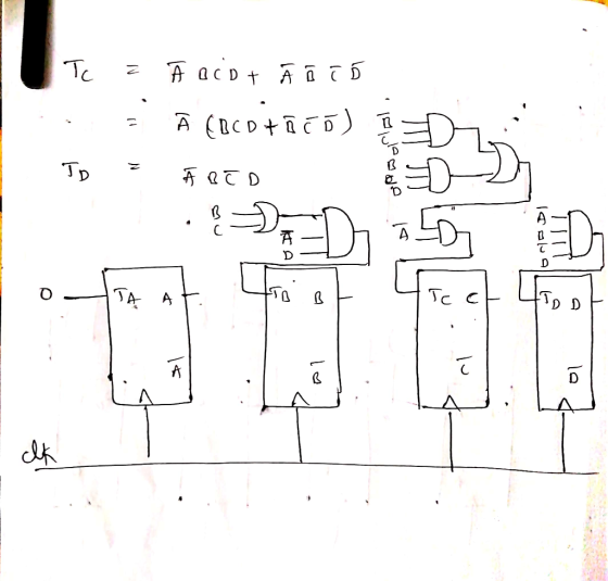
Design a self-starting counter that has a normal counting sequence : 3, 7,5,0,2, and repeat. Direct...
Design a self-starting counter that has a normal counting sequence : 3, 7,5,0,2, and repeat. Direct all illegal states to the state 5.
(a) Use T flip-flops
(b) Use D flip-flops
(PLEASE USING CBA )
Homework Answers


Add Answer to:
Design a self-starting counter that has a normal counting
sequence : 3, 7,5,0,2, and repeat. Direct...
In this part, design a counter with a specific counting sequence (counter with irregular sequence) as...
In this part, design a counter with a specific counting sequence (counter with irregular sequence) as described in Table 2 below by using positive edge triggered D flip-flops. N=8, Counting sequence 8 0, 1, 7, 5, 3, 6, 4, 2, … (repeat)
Design a 3-bit counter with counting sequence of 1, 3, 7, 2. Note: Use the symbol...
Design a 3-bit counter with counting sequence of 1, 3, 7, 2. Note: Use the symbol in order of CBA. (1) Draw the resulting circuit using JK-type flip flops. (2) Draw the complete state diagram corresponding to your circuit.
3. Design a counter with the following repeated binary sequence: 0,1,2,4,6. Use D flip-flop.
3. Design a counter with the following repeated binary sequence: 0,1,2,4,6. Use D flip-flop. 4. Design a counter to count with T flip-flops that goes through the following binary repeated sequence: 0,1,3,7,6,4. Find out the counter response towards the unused state. Illustrate the response with a state diagram. 5. Design a mod-7 counter (repeat binary sequence: 0,1,2,3,4,5,6) use JK flip-flop.
Using S-R flip-flops, design a 3-bit counter (C,B,A) with the repeating binary counting sequence: 1, 3,...
Using S-R flip-flops, design a 3-bit counter (C,B,A) with the repeating binary counting sequence: 1, 3, 2, 6, 7, 5, 4. - Show the circuit's state table with the present-state entries in ascending order, which should have the present state (t), next state (t+1), and flip-flop inputs. - Find the flip-flop input equations for RC, RB, and RA in Product of Sums form.
(b)(i) Using T flip-flop as main components, design a 3-bit synchronous counter that perform counting as...
 (b)(i) Using T flip-flop as main components, design a 3-bit synchronous counter that perform counting as the following sequence 0,2,4,6,1,3,5,7 then repeats (its sequence) [20 marks] (ii) Draw a complete circuit to show how the T flip-flops are interconnected and label it appropriately. Also show how the counter can be asynchronous reset. [5 marks] (iii) Draw a timing diagram for at least four clock cycles [8 marks)
Its logic design my sequence is 127605 i need help with all this pages please and thank you
 Its logic design
my sequence is 127605
i need help with all this pages please and thank you
27 60 Experiment 4 Six-State Up-Down Counter 1 Objective To become familiar with the design procedures of a counter, which are applicable to the design of other synchronous sequential circuits. 2 Problem description A six-state up-down counter is to be designed. Three flip-flops with outputs Q2,Qi and Qo are required in the design. As shown in Figure 1, the counter is initialized...
Its logic design
my sequence is 127605
i need help with all this pages please and thank you
27 60 Experiment 4 Six-State Up-Down Counter 1 Objective To become familiar with the design procedures of a counter, which are applicable to the design of other synchronous sequential circuits. 2 Problem description A six-state up-down counter is to be designed. Three flip-flops with outputs Q2,Qi and Qo are required in the design. As shown in Figure 1, the counter is initialized...
A counter to display the following sequence: 4,5,3,6, flip-flops in your design. Display the outp...
 a counter to display the following sequence: 4,5,3,6, flip-flops in your design. Display the output using a 7-segment display. 1. Design 2, 7, 1, 0, and then repeat. Use JK
a counter to display the following sequence: 4,5,3,6, flip-flops in your design. Display the output using a 7-segment display. 1. Design 2, 7, 1, 0, and then repeat. Use JK
a counter to display the following sequence: 4,5,3,6, flip-flops in your design. Display the output using a 7-segment display. 1. Design 2, 7, 1, 0, and then repeat. Use JK
Design a counter circuit with sequence 0, 1, 2, …, 11 and repeat using JK flip-flops....
Design a counter circuit with sequence 0, 1, 2, …, 11 and repeat using JK flip-flops. Design the circuit with pen and paper and then simulate it using Logisim (justify the input values chosen)
Use D flip-flops to design a 3-bit counter
 Use D flip-flops to design a 3-bit counter which counts in the sequence: 110, 100,
101, 111, 011, 010, 001, (repeat) 110, . . .
In this case, what will happen if the counter is started in state 000?
Use D flip-flops to design a 3-bit counter which counts in the sequence: 110, 100,
101, 111, 011, 010, 001, (repeat) 110, . . .
In this case, what will happen if the counter is started in state 000?
Design a 3-bit counter that has only one input, w. It counts down 7, 6,5,... 0, 7,.. whenever w-0...
 all please
Design a 3-bit counter that has only one input, w. It counts down 7, 6,5,... 0, 7,.. whenever w-0, and counts up 0,1,2...7,0... when w 1 The output z-1, when the state of the counter is a prime number. Otherwise, z-0 1. List Inputs, Outputs and the count sequence. (5pts) 2. Draw the finite State machine for the counter. (10pts) 3. Draw the state transition table <extra columns for the flip flops values> (20pts) armed resource/content/1/case%20study.template.docx 4. Design...
all please
Design a 3-bit counter that has only one input, w. It counts down 7, 6,5,... 0, 7,.. whenever w-0, and counts up 0,1,2...7,0... when w 1 The output z-1, when the state of the counter is a prime number. Otherwise, z-0 1. List Inputs, Outputs and the count sequence. (5pts) 2. Draw the finite State machine for the counter. (10pts) 3. Draw the state transition table <extra columns for the flip flops values> (20pts) armed resource/content/1/case%20study.template.docx 4. Design...
 (b)(i) Using T flip-flop as main components, design a 3-bit synchronous counter that perform counting as the following sequence 0,2,4,6,1,3,5,7 then repeats (its sequence) [20 marks] (ii) Draw a complete circuit to show how the T flip-flops are interconnected and label it appropriately. Also show how the counter can be asynchronous reset. [5 marks] (iii) Draw a timing diagram for at least four clock cycles [8 marks)
 Its logic design
my sequence is 127605
i need help with all this pages please and thank you
27 60 Experiment 4 Six-State Up-Down Counter 1 Objective To become familiar with the design procedures of a counter, which are applicable to the design of other synchronous sequential circuits. 2 Problem description A six-state up-down counter is to be designed. Three flip-flops with outputs Q2,Qi and Qo are required in the design. As shown in Figure 1, the counter is initialized...
Its logic design
my sequence is 127605
i need help with all this pages please and thank you
27 60 Experiment 4 Six-State Up-Down Counter 1 Objective To become familiar with the design procedures of a counter, which are applicable to the design of other synchronous sequential circuits. 2 Problem description A six-state up-down counter is to be designed. Three flip-flops with outputs Q2,Qi and Qo are required in the design. As shown in Figure 1, the counter is initialized...
 a counter to display the following sequence: 4,5,3,6, flip-flops in your design. Display the output using a 7-segment display. 1. Design 2, 7, 1, 0, and then repeat. Use JK
a counter to display the following sequence: 4,5,3,6, flip-flops in your design. Display the output using a 7-segment display. 1. Design 2, 7, 1, 0, and then repeat. Use JK
a counter to display the following sequence: 4,5,3,6, flip-flops in your design. Display the output using a 7-segment display. 1. Design 2, 7, 1, 0, and then repeat. Use JK
 all please
Design a 3-bit counter that has only one input, w. It counts down 7, 6,5,... 0, 7,.. whenever w-0, and counts up 0,1,2...7,0... when w 1 The output z-1, when the state of the counter is a prime number. Otherwise, z-0 1. List Inputs, Outputs and the count sequence. (5pts) 2. Draw the finite State machine for the counter. (10pts) 3. Draw the state transition table <extra columns for the flip flops values> (20pts) armed resource/content/1/case%20study.template.docx 4. Design...
all please
Design a 3-bit counter that has only one input, w. It counts down 7, 6,5,... 0, 7,.. whenever w-0, and counts up 0,1,2...7,0... when w 1 The output z-1, when the state of the counter is a prime number. Otherwise, z-0 1. List Inputs, Outputs and the count sequence. (5pts) 2. Draw the finite State machine for the counter. (10pts) 3. Draw the state transition table <extra columns for the flip flops values> (20pts) armed resource/content/1/case%20study.template.docx 4. Design...
Most questions answered within 3 hours.
-
Where is the error in this code sequence?
String s1 = "Hello";
String s2 = "ello";...
asked 10 months ago -
Financial data for Joel de Paris, Inc., for last year
follow:
Joel de Paris, Inc.
Balance...
asked 10 months ago -
Consider this reaction:
Al2(SO4)3 (aq)+ BaCl3
(aq) Al2Cl6 (aq)- +
3BaSO4(s) . What is the...
asked 10 months ago -
Suppose that Savneet is considering increasing her
recent random sample from 20 car rentals to 40...
asked 10 months ago -
Trucks arrive at an unloading terminal at an average rate of 120
per hour.
Trucks arrive...
asked 10 months ago -
Why are methanol and ethanol completely soluble in water while
octanol is not very little soluble....
asked 10 months ago -
A facilities manager at a university reads in a research report
that the mean amount of...
asked 10 months ago -
When the CuSO4 is rehydrated by adding water to the anhydrous
compound, is this an endothermic...
asked 10 months ago -
A ray of sunlight is passing from diamond into crown glass; the
angle of incidence is...
asked 10 months ago -
A block of mass 0.249 kg is placed on top of a light, vertical
spring of...
asked 10 months ago -
how do the kidneys compensate in the presences of acidosis
a) trigger hyperventilate
b) reserve acid...
asked 10 months ago -
Question 501 pts
The rental rate of capital to the firm increases. Which of the
following...
asked 10 months ago