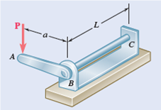
The solid cylindrical rod BC of length L = 24 in. is attached to the rigid lever AB of len...
The solid cylindrical rod BC of length L = 24 in. is attached to the rigid lever AB of length a = 15 in. and to the support at C. Design specifications require that the displacement of A not exceed 1 in. when a 100-lb force P is applied at A. For the material indicated, determine the required diameter of the rod.
Steel: τall = 15 ksi, G = 11.2 × 10⁶ psi.
Fig. P10.39
Step-by-Step Solution
Calculate the Torque applied on the shaft due to the force applied at \(A\).
$$ T=P \times a $$
Here, \(P\) is the applied load, \(a\) is distance of line of action of force from axis of shaft.
Substitute \(100 \mathrm{lb}\) for \(P\) and 15 in for \(a\).
$$ \begin{aligned} T &=(100 \mathrm{lb})(15 \mathrm{in} .) \\ &=1500 \mathrm{lb} \cdot \mathrm{in} . \end{aligned} $$
Write the equation for the allowable shear stress of a solid shaft.
$$ \tau_{\mathrm{all}}=\frac{16 T}{\pi d^{3}} $$
$$ d=\left(\frac{16 T}{\pi \tau_{\mathrm{all}}}\right)^{\frac{1}{3}} $$
Here, \(\tau_{\text {all }}\) is the allowable shear stress.
Substitute \(1500 \mathrm{lb} \cdot \mathrm{in}\). for \(T\) and \(15 \times 10^{3} \mathrm{lb} / \mathrm{in} .{ }^{2}\) for \(\tau_{\mathrm{all}}\)
$$ \begin{aligned} d &=\left[\frac{16(1500 \mathrm{lb} \cdot \mathrm{in} .)}{\pi\left(15 \times 10^{3} \mathrm{lb} / \mathrm{in} .^{2}\right)}\right]^{\frac{1}{3}} \\ &=0.8 \mathrm{in} . \end{aligned} $$
Calculate the maximum allowable angular twist.
$$ \phi_{\text {all }}=\frac{s_{\max }}{\mathrm{a}} $$
Here, \(s_{\max }\) is the maximum allowable displacement of point \(A\) and \(a\) is the distance of the line of action of force from the axis of the shaft.
Substitute \(0.1\) in. for \(s_{\max }\) and 15 in. for \(a\).
$$ \begin{aligned} \phi_{\text {all }} &=\frac{1 \mathrm{in} .}{15 \mathrm{in} .} \\ &=0.067 \mathrm{rad} \end{aligned} $$
This angular twist is same for both \(B\) and point \(A\).
Write the equation for the angular of twist in the shaft.
$$ \begin{array}{l} \phi=\frac{T L}{J G} \\ \phi_{\text {all }}=\frac{T L}{\frac{\pi}{32} d^{4} G} \\ d=\left(\frac{32 T L}{\pi G \phi_{\text {all }}}\right)^{\frac{1}{4}} \end{array} $$
Here, \(G\) is the rigidity modulus of the shaft.
Substitute \(11.2 \times 10^{6} \mathrm{lb} / \mathrm{in} .{ }^{2}\) for \(G, 1500 \mathrm{lb} \cdot \mathrm{in} .\) for \(T, 15 \times 10^{3} \mathrm{lb} / \mathrm{in} .{ }^{2}\) for \(\tau_{\mathrm{all}}, 24 \mathrm{in} .\) for \(L\), and
\(0.067 \mathrm{rad}\) for \(\phi_{\text {all }}\).
$$ d=\left[\frac{32(1500 \mathrm{lb} \cdot \mathrm{in} .)(24 \mathrm{in} .)}{\pi\left(11.2 \times 10^{6} \mathrm{lb} / \mathrm{in}^{2}\right)(0.067)}\right]^{1 / 4} $$
\(=0.837\) in.
Consider the two values obtained, the higher value holds the key for the design condition considering the minimum required diameter.
Hence, the minimum diameter of the shaft is \(0.837\) in.
Most questions answered within 3 hours.
-
Calculating the space time for parallel reactions. m-Xylene is reacted over a ZSM-5 zeolit...
-
Determine Vo and ID for the networks of Fig. 2.160.FIG. 2.160
-
The truck travels along a circular road that has a radius of 50 m at a speed of 4 m/s. F...
-
A state legislature enacted a statute that required any motorcycle operator or passenger...
-
A 1024 × 1024 8-bit image with 5.3 bits/pixel entropy [computed from its histogram using E...
-
In Problem 3.3, we estimated the equationwhere we now report standard errors along with th...
-
In each of the following cases, deduce the nature of the light that is consistent with the...
-
Solve Example 20.5 such that the x, y, z axes move with curvilinear translation, Ω = 0 in...
-
In Fig. 6.43, if i = cos 4t and v = sin 4t, the element is:(a)a resistor(b) a capacitor(c)...
-
Sketch vo for each network of Fig. 2.181 for the input shown.FIG. 2.181
-
(Supplement B) Computing and Reporting Cash Flow Effectsof Sale of Plant and EquipmentDuri...
-
A 350-mL spherical flask contains 0.075 mol of an ideal gas at a temperature of 293 K. Wha...